215916 210 Revision A
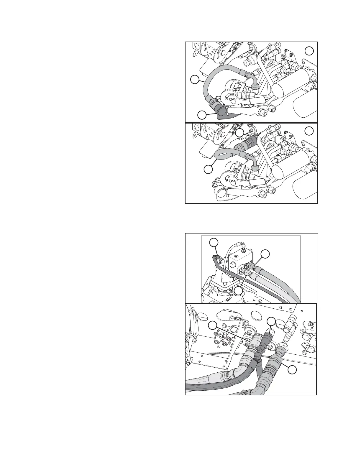
Figure 4.222: Knife Pressure Hose Positions
1 - Knife Pressure Hose in Storage Position – Rotary Configuration
2 - Hose to Knife Pressure Receptacle – Auger/Draper Configuration
5. If switching from an auger/draper header to a rotary
header: Disconnect hose (A) from knife pressure
receptacle (C) on the frame, and move it to storage
location (B).
Figure 4.223: Hydraulics and Electrical
6. Connect the hydraulic hoses to a windrower with quick
coupler fittings as follows:
a. Connect disc pressure hose (A) with coupler (B). Torque
the connection to 216 Nm (159 lbf·ft).
b. Connect disc return hose (C) with coupler (D). Torque
the connection to 216 Nm (159 lbf·ft).
c. Connect case drain hose (E) to fitting (F), with the relief
valve pointing towards the ground.
NOTE:
If required, loosen fitting (F) and retighten it as needed to
ensure that the relief valve is pointing straight down.
OPERATION