215916 215 Revision A
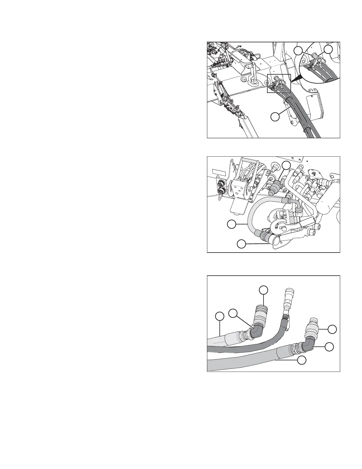
Figure 4.233: Hose Support Attachment
1. Retrieve hydraulic hoses (A) from the header and route the
hose bundle under the windrower frame.
NOTE:
Adding anti-seize compound to the hose holder pin will
make future removal easier.
2. Insert pin (B) into hole (C) in the windrower frame.
IMPORTANT:
Route the hydraulic hoses as straight as possible, avoiding
wear points that could damage the hoses. To prevent
abrasion damage, the hoses should have enough slack to
pass by the multicoupler bracket without contacting it. To
adjust the slack in the hoses, loosen the clamps below
pin (B), adjust the hoses, then retighten the hose holder.
Figure 4.234: Couplers – Auger/Rotary Disc/Draper-
Ready Configuration
3. Ensure that hose (A) is disconnected from windrower
receptacle (B) and placed in storage cup (C) on the
multicoupler.
Figure 4.235: Header Hydraulic Fittings
4. Connect the hydraulic fittings to the hydraulic hoses as
follows:
NOTE:
The two quick couplers and two elbow fittings are supplied
in the Quick Coupler kit (MD #B6277).
a. Attach 90° elbow fitting (A) and 1 in. female coupler
fitting (B) to disc pressure hose (C).
b. Attach 90° elbow fitting (A) and 1 in. male coupler
fitting (D) to disc return hose (E).
OPERATION