215916 10 Revision A
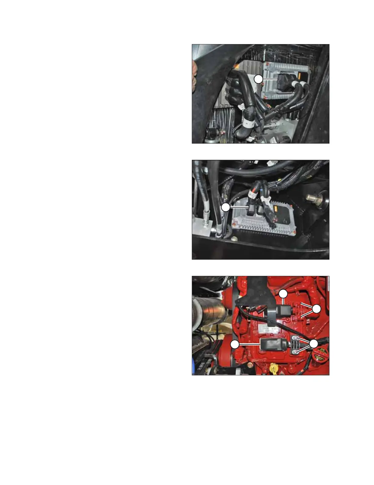
Figure 1.21: Firewall Extension Module
• Firewall extension module (A)
Two connectors: P235 and P236
Location: Behind the cab, near the header lift/fan manifold
To disconnect the connectors, insert the end of a a small
3–6 mm (1/8–1/4 in.) blade screwdriver into the connector’s
locking tab. Gently pry upward (no more than 6 mm [1/4
in.]) to unlock the connector tab, and then pull the
connector away from the module.
Figure 1.22: Chassis Extension Module
• Chassis extension module (A)
Two connectors: P247 and P248
Location: Under the cab, inside the left frame rail
To disconnect the connectors, insert the end of a small
3–6 mm (1/8–1/4 in.) blade screwdriver into the connector’s
locking tab. Gently pry upward (no more than 6 mm
[1/4 in.]) to unlock the connector tab, and then pull the
connector away from the module.
Figure 1.23: Engine Control Module
• Engine Control Module (ECM)
Two connectors for Cummins: P100 (A) and J1 Cummins
Proprietary ECM Connector (B)
Location: On the engine
To disconnect the connectors, pull the rubber boot off of
the cover, unlock the latch, and undo the main over-center
latch. Remove strain relief bolts (C) so that the connectors
can be pulled away from the ECM.
IMPORTANT:
Be sure to disconnect both connectors. Note the connector
locations for reinstallation.
IMPORTANT:
Be sure to reconnect the connectors in the proper locations.
Do NOT cross connect the connectors.
SAFETY