ND-70348 (E) CHAPTER 4
Page 172
Revision 5.0
ASYD
Note 1:
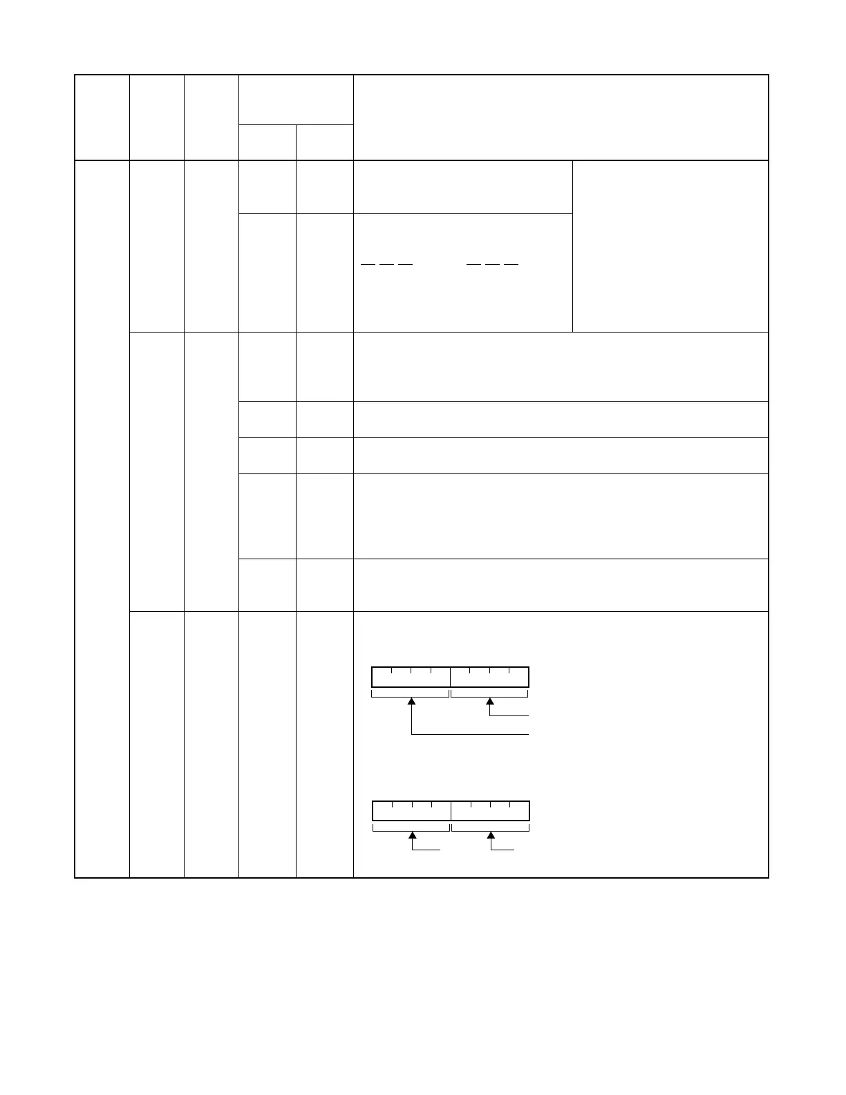
When these data have been set as specified below, the alarm message output value becomes 80% and the
alarm message output clear message output value becomes 50% regardless of the data.
• When the data of INDEX 249 is smaller than or equal to the data of INDEX 250
• When these data values are not valid.
SYSTEM
DATA
TYPE
(SYS)
SYSTEM
DATA
INDEX
(INDEX)
0 – 511
DATA
(DATA)
00 – FF
(Hex)
BIT
CORRESPONDING
DATA
SYSTEM DATA CONTENTS
DATA
0/1
BIT
1
247
b
0
~b
3
Miscellaneous Timer Counter (MTC)
is to be assigned a value from 0 Hex to
F Hex (0~15)
No Answer Timer for Blind
Transfer-station
Timer Value Setting is MTC
×
TC
sec.
Note:
When this data is 00 hex,
default data is automati-
cally set to 30 sec.
b
4
~b
7
Timer Class (TC) is to be assigned one
of the following values:
248
b
0
~b
3
Maximum Number of Digits for Call Forwarding – Toll Restriction
0: 12 digits A: 10 digits
1-8: 8 digits B: 11 digits
9: 9 digits C-F: 12 digits
b
4
Call Forward Don’t Answer After Attendant Camp-On
0/1 = No/Yes
b
5
Malicious Call Trace (MCT)/Malicious Call Indentification (MCID)
0/1 = Out of Service/In Service
b
6
When the destination station has been set Call Forwarding - Don’t Answer
0 = Recall to the station
1 = C.F. - Don’t Answer is activated
Note:
Valid since software Release 7 for Australia, Release 9 for other
countries.
b
7
Tone to be sent out when the handset is off-hook at the station on which
C.F. – All Calls service is set.
0/1 = Dial Tone (DT)/Special Dial Tone (SPDT)
249
b
0
~b
7
SMDR output buffer usage rate (01–99%) at the time of output of SMDR
Buffer Overflow Alarm message (System Message 6-O)
Note 1
Example:
Indicates that the usage rate has been set to 80%.
b
6
0
0
0
0
b
5
0
0
1
1
b
4
0
1
0
1
=–
=–
=–
= 2 sec.
b
6
1
1
1
1
b
5
0
0
1
1
b
4
0
1
0
1
=–
=–
=–
= 8 sec.
b
7
b
6
b
5
b
4
b
3
b
2
b
1
b
0
Unit
Tens
b
7
b
6
b
5
b
4
b
3
b
2
b
1
b
0
8
0
10 000 000
 Loading...


