ND-70348 (E) CHAPTER 4
Page 652
Revision 4.0
AIECN
3. Data Entry Instructions
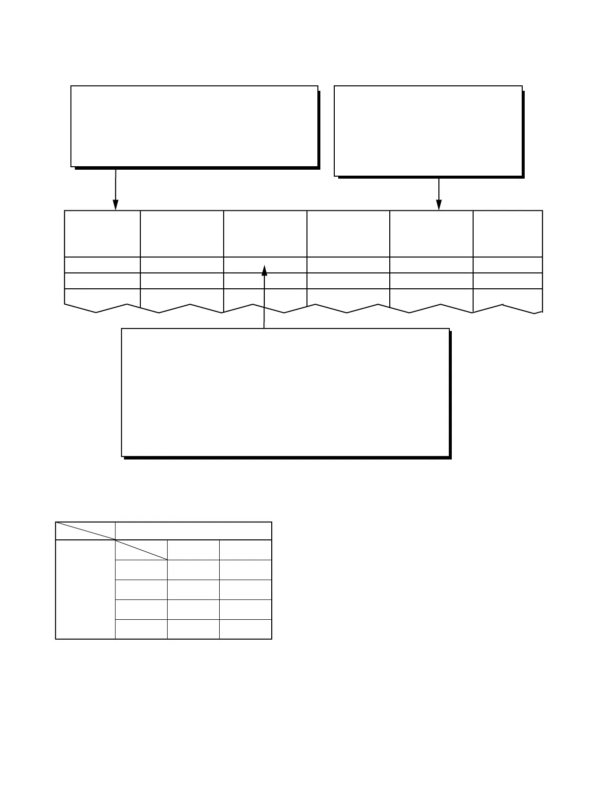
Note:
According to the combination of Terminal A and Terminal B, required parameters vary as shown in the ta-
ble below.
TERMINAL A
[NODE/IPG]
A NODE/
A IPG
TERMINAL B
[LGRT/TEC/
NODE/IPG]
B LGRT/
B TEC/
B NODE/
B IPG
ECHO
CANCELER
CONTROL
TYPE
(EC)
REMARKS
TERMINAL A
TERMINAL B
Click the required check box according to each terminal.
Then assign the data in NODE/IPG parameter.
NODE: Node Number on which IPTRK card is
accommodated. [Max. 3 digits (0-9, *, #, P)]
IPG: IPELC Group Data [0-127]
EC
Select the Echo Canceler Control Type
from the following patterns. Note
Pattern 1 → A EC-ON/B EC-ON
Pattern 2 → A EC-ON/B EC-OFF
Pattern 3 → A EC-OFF/B EC-ON
Pattern 4 → A EC-OFF/B EC-OFF
Click the required check box according to each terminal. Then assign the
data in LGRT/TEC/NODE/IPG parameter.
LGRT: Logical Route Number of the trunk [1-899, 901-947 (not
used now)]
TEC: Telephone Equipment Class of the station [1-4, 12, 14, 23,
26-28]
NODE: Node Number on which IPTRK card is accommodated
[Max. 3 digits (0-9, *, #, P)]
IPG: IPELC Group Data [0-127]
TERMINAL A
TERMINAL
B
NODE IPG
LGRT
II
TEC
II II
NODE
I-
IPG
II
I: Any pattern can be assigned.
II: Either Pattern 2 or 4 can be selected.
 Loading...


