Serial bus analysis
R&S
®
RTM3000
275User Manual 1335.9090.02 ─ 09
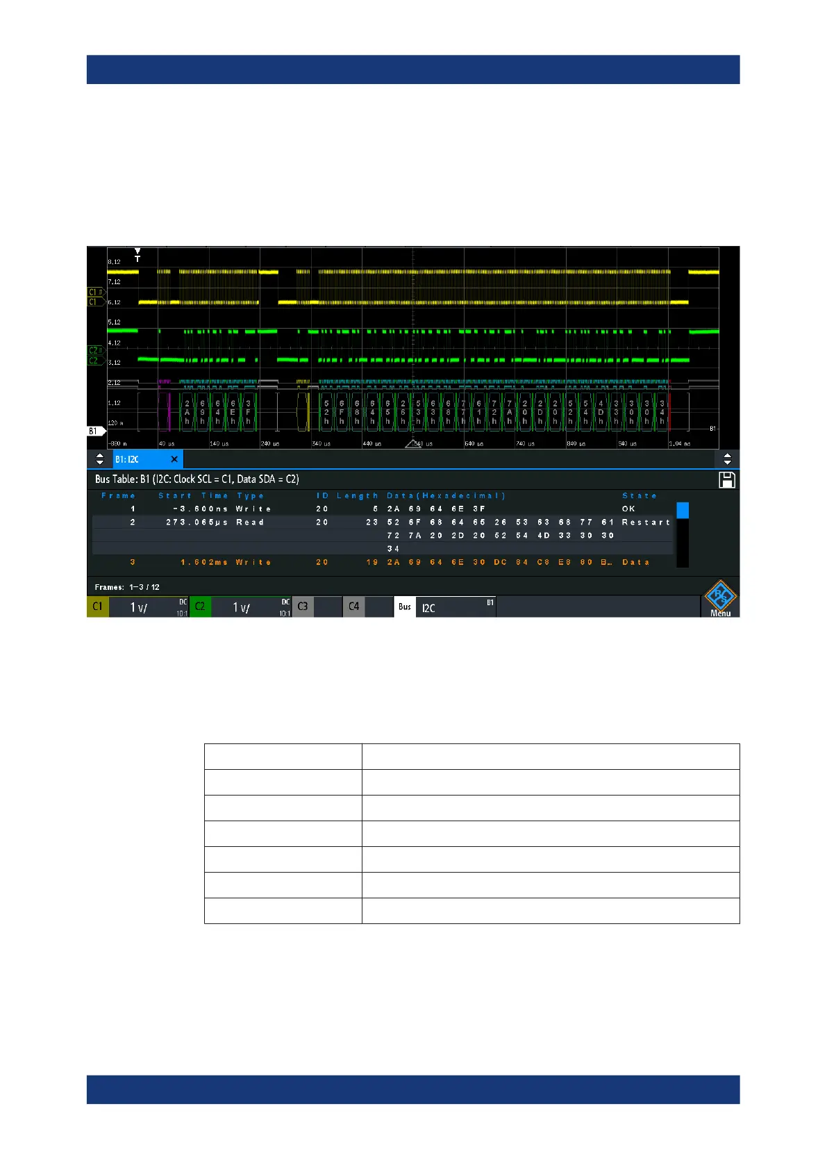
The instrument captures and decodes the signal according to the protocol definition
and the configuration settings.
The color-coding of the various protocol sections and errors simplifies the interpretation
of the visual display. The decode information condenses or expands, depending on the
horizontal scale. Various data formats are available to show the result values.
Figure 13-14: Decoded I2C signal with bus table, trigger on frame start
Gray brackets = start and end of the frame
Violet = address
Blue = correct data words
Green = acknowledge bit, ok
Table 13-2: Content of the I
2
C frame table
Column Description
Start time Time of the frame start in relation to the trigger point
Type Value of the R/W bit, read or write access
ID Hexadecimal value of the address
Length Number of words in the frame
Data Hexadecimal values of the data words
State Overall state of the frame
Remote commands are described in Chapter 17.11.3.3, "I²C - decode results",
on page 622.
I²C (option R&S
RTM-K1)
 Loading...


