Trigger
R&S
®
RTM3000
91User Manual 1335.9090.02 ─ 09
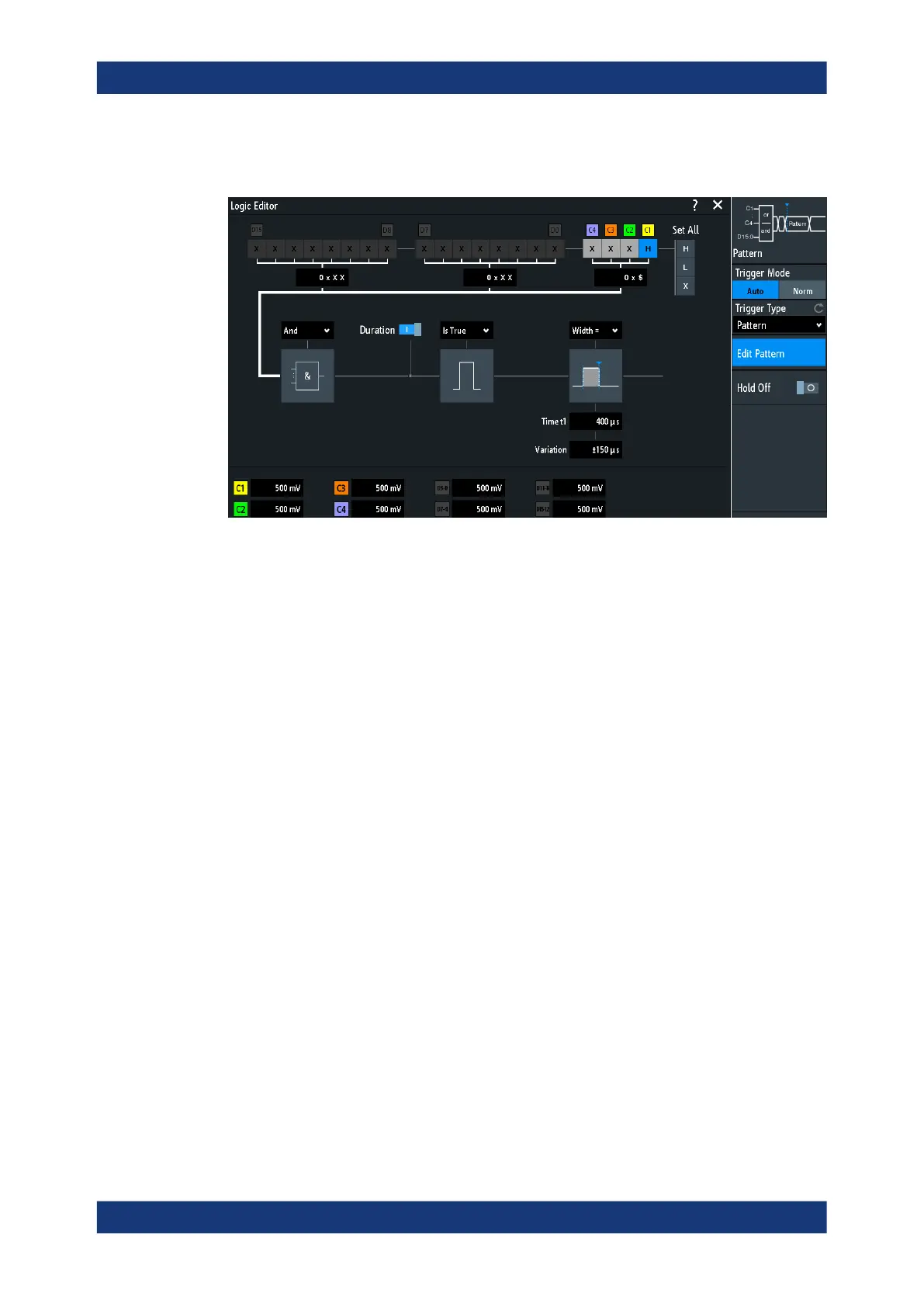
► [Trigger] > "Trigger Type" = "Pattern" > "Edit Pattern"
Figure 6-7: Pattern trigger with logic editor
Thresholds
At the bottom of the "Logic Editor", you see the current threshold settings of all chan-
nels. Here, you can directly activate the channels, and change the threshold values.
The thresholds of analog channels are also set in the "Channel <n>" > "Threshold"
menu, see also Chapter 5.3.4, "Threshold settings", on page 59.
The thresholds of logic channels are also set in the [Logic] > "Threshold and Deskew"
dialog, see Chapter 15.2, "Logic analyzer settings", on page 394.
Logic settings
H | L | X, Set All.............................................................................................................91
And | Or.........................................................................................................................92
Duration.........................................................................................................................92
True | False................................................................................................................... 92
Time limitation............................................................................................................... 92
H | L | X, Set All
Defines the pattern by selecting the state "H" (high), "L" (low) or "X" (do not care) for
each active analog and digital channel.
The word length of the pattern depends on the number of available analog and digital
channels.
Analog channels: 2 bit for 2-channel instruments, 4 bit for 4-channel instruments.
Digital (16 bit): the logic channels D0, D1,...,D15 are only available with MSO option
R&S RTM-B1.
Thus the pattern can have 2, 4, 18, or 20 bits.
Use "Set All" to set all channels to the same state.
Pattern trigger