H1: Manual and handwheel travel
3.1 Introduction
Extended Functions
Function Manual, 03/2013, 6FC5397-1BP40-3BA1
147
Spindle manual travel
Spindles can also be traversed manually in JOG mode. Essentially, the same conditions
apply as for manual travel of axes. Spindles can be traversed in JOG mode using the
traversing keys continuously or incrementally, in jog or continuous mode, or using the
handwheel. The mode is selected and activated via the axis-/spindle-specific PLC interface
as for the axes. The axis-specific machine data also applies to the spindles. Special features
relating to the manual traversal of spindles are described in "Spindle manual travel
(Page 211)".
3.1.3 Control of manual-travel functions via PLC interface
The manual traversing functions in the NC are activated via the NC/PLC interface from the
machine control panel (MCP). To do this, the input signals of the machine control panel from
the PLC must be transferred to the input interface of the NC in the NC/PLC interface. In this
way, the machine manufacturer can simply adapt the manual traversing functionality to the
machine tool through the PLC user program. You can use this, for example, to change the
assignment between the direction keys of the machine control panel and the traversing
requests to the NC with regard to the machine and geometry axes.
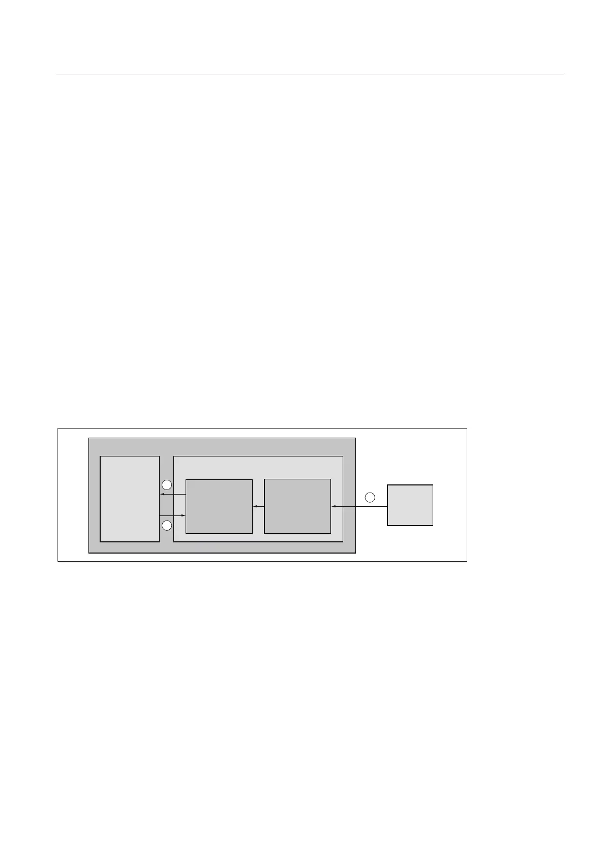
Basic procedure
The following figure shows the basic procedure for the selection of JOG mode from the
machine control panel (MCP) to the NC.
3/&
1&8
1&
0&3
%DVLF
3/&
SURJUDP
3/&
XVHU
SURJUDP
1
2
3
① The operator selects, for example, the "Continuous JOG" machine function on the machine control panel for a
machine axis.
The input signals of the MCP are transferred cyclically from the basic PLC program in the data blocks of the MCP
input interface.
② The PLC user program reads the input signals of the MCP. The input signals can be linked with any other signals in
accordance with the current machine or machining situation. Finally, the PLC user program writes the
corresponding request signals to the NC in the respective axial NC/PLC interface.
The basic PLC program transfers the request signals in the internal input interface to the NC.
③ After activation of the requested function, the NC writes the feedback in the internal output interface to the PLC. The
basic PLC program cyclically transfers the output signals in the respective axial NC/PLC interface

 Loading...


