N3: Software cams, position switching cycles - only 840D sl
8.2 Cam signals and cam positions
Extended Functions
536 Function Manual, 03/2013, 6FC5397-1BP40-3BA1
8.2 Cam signals and cam positions
8.2.1 Generation of cam signals for separate output
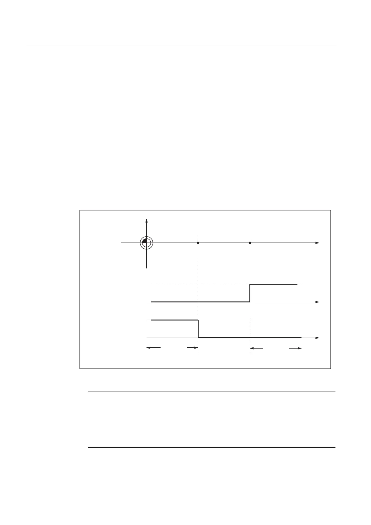
Separate output of the plus and minus cam signals makes it easy to detect whether the axis
is within or outside the plus or minus cam range.
Linear axes
The switching edges of the cam signals are generated as a function of the axis traversing
direction:
● The minus cam signal switches from 1 to 0 when the axis traverses the minus cam in the
positive axis direction.
● The plus cam signal switches from 0 to 1 when the axis traverses the plus cam in the
positive direction.
0LQXVFDPVLJQDO
3OXVFDPVLJQDO
0DFKLQH
]HUR
0DFKLQHD[LV>P@
>PPLQFK@
0DFKLQHD[LV>Q@
SOXVFDP
FDPSRVLWLRQ
PLQXVFDP
FDPSRVLWLRQ
SOXV
&DPUDQJH
&DPUDQJH
PLQXV
Figure 8-1 Software cams for linear axis (minus cam < plus cam)
Note
If the axis is positioned exactly at the output cam position (plus or minus), the defined
output flickers. If the axis moves one increment further, the output becomes a definite
zero or one.
Flickering of the actual position causes the signals to flicker in this manner.
The actual position is evaluated.

 Loading...


