B3: Distributed systems - 840D sl only
2.3 Examples
Extended Functions
Function Manual, 03/2013, 6FC5397-1BP40-3BA1
135
2.3.5 Lead link axis
2.3.5.1 Configuration
$;$;
&RXSOHGD[HVRQOHDGLQJD[LV1&B$;ZLWK
=/$;RQ1&8DQG=/$;RQ1&8QDV
OHDGOLQND[HV
0DVWHU
D[LV
/HDGOLQND[HV
)ROORZLQJ
D[HV
1&8Q
/$;/$; /$;
=<;
1&81&8
$;$;
/$;/$; /$;
=<;
$;
$;
$;
/$;/$; /$;
=<;
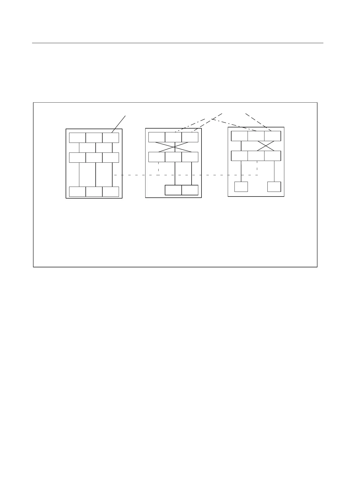
Figure 2-24 NCU2 to NCUn use a lead link axis to enable coupling to the machine axis on NCU1 (NCU1-AX3).
The following example refers to the axis coupling section between Y(LAX2, AX2) as
following axis on NCU2 and Z(LAX3, NC1_AX3) as lead link axis.
Machine data
● The machine data of a leading value axis may only be loaded on the home NCU. From
this NCU, the relevant machine data are distributed to the other NCUs where a lead link
axis has been defined.
● Each lead link axis reduces the maximum number of axes that can be traversed on this
NCU by one axis.

 Loading...


