K3: Compensations
4.2 Temperature compensation
Extended Functions
Function Manual, 03/2013, 6FC5397-1BP40-3BA1
229
4.2.3 Example
4.2.3.1 Commissioning the temperature compensation for the Z axis of a lathe
Commissioning of temperature compensation is described below using the example of a Z
axis on a lathe.
Determining the error characteristic of the Z axis
In order to determine the temperature-dependent error characteristic of the Z axis, proceed
as follows:
● Uniform temperature increase by traversing the axis across the whole Z axis traversing
range (in the example: from 500 mm to 1500 mm)
● Measuring the axis position in increments of 100 mm
● Measuring the actual temperature at the leadscrew
● Executing a traversing measuring cycle every 20 minutes
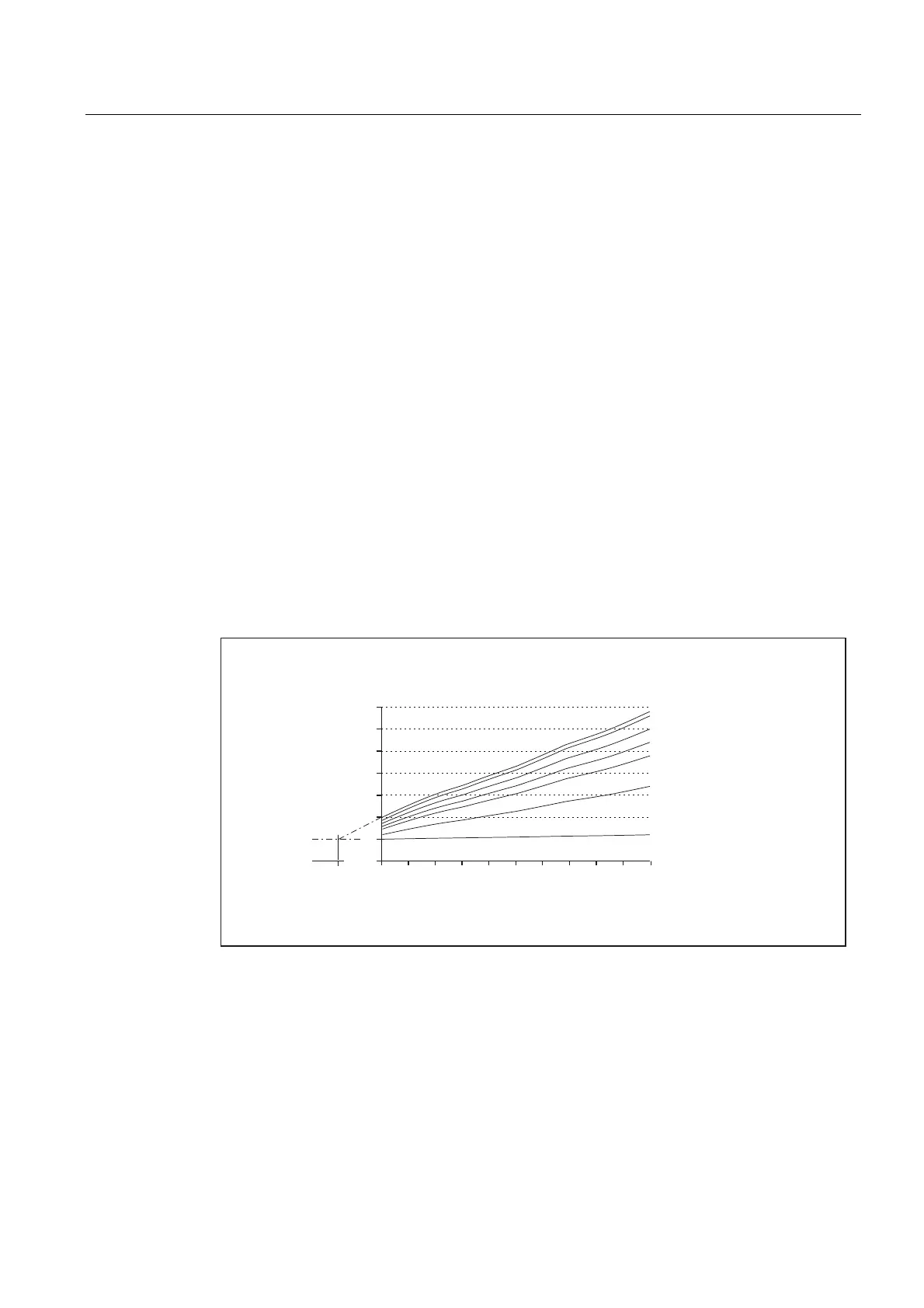
The mathematical and technological relationships and the resulting parameters for
temperature compensation are derived from the recorded data. The calculated deviation
errors for a specific temperature, which refer to the actual position of the Z axis displayed by
the NC, are represented in graphic form in the diagram below.
3RVLWLRQRIWKH=D[LV>PP@
0HDVXUHGWHPSHUDWXUH
GHJUHHV
GHJUHHV
GHJUHHV
GHJUHHV
GHJUHHV
GHJUHHV
GHJUHHV
5HIHUHQFH
SRLQW3
$EVHUURUGHYLDWLRQ>˩P@
Figure 4-2 Error curves determined for the Z axis

 Loading...


