Z2: NC/PLC interface signals
18.3 Manual and Handwheel Travel (H1)
Extended Functions
858 Function Manual, 03/2013, 6FC5397-1BP40-3BA1
18.3 Manual and Handwheel Travel (H1)
18.3.1 Signals from NC (DB10)
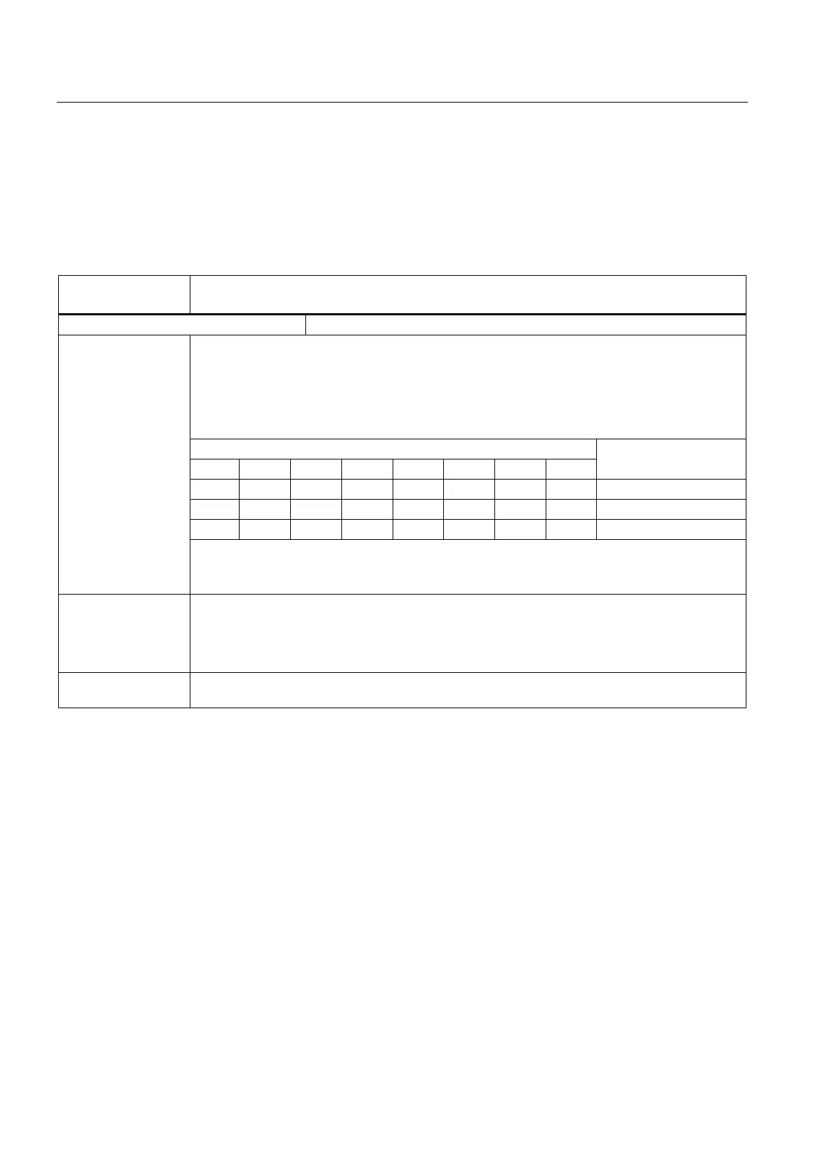
DB10
DBB97, 98, 99
Channel number geometry axis for handwheel 1, 2, 3
Edge evaluation: No Signal(s) updated: Cyclic
The operator can assign an axis to the handwheel (1, 2, 3) directly on the operator panel front. If
this axis is a geometry axis (IS "Machine axis" = 0), the assigned channel number for the
handwheel in question is transferred to the PLC.
In this way, the IS "Activate handwheel" is set for the selected geometry axis in accordance with
the state set by the operator (IS "Handwheel selected").
The following codes apply to the channel number:
Bit
7 6 5 4 3 2 1 0
Channel number
0 0 0 0 0 0 0 0 -
0 0 0 0 0 0 0 1 1
0 0 0 0 0 0 1 0 2
Significance of signal
With machine axes (IS "Machine axis" = 1), the IS "Channel number geometry axis for handwheel
1, 2, 3" has no meaning.
For further information, see IS "Axis number for handwheel 1, 2, 3".
Corresponding to .... DB10 DBB100 ff (axis number for handwheel 1, 2, 3)
DB10 DBX100.6 ff (handwheel selected)
DB10 DBX100.7 ff (machine axis)
DB21, ... DBX12.0 - 12.2 ff (activate handwheel)
Application
example(s)
If DB10 DBB97 = 2, then handwheel 1 is assigned to channel 2.

 Loading...


