M5: Measurement
7.5 Setting zeros, workpiece measuring and tool measuring
Extended Functions
Function Manual, 03/2013, 6FC5397-1BP40-3BA1
477
Input variable Meaning
$AA_MEAS_POINT4[axis] When specified, the center is determined from four points
*
$AA_MEAS_SETPOINT[axis] Setpoint position of shaft center point *
$AC_MEAS_ACT_PLANE Calculated as active plane unless otherwise specified *
$AC_MEAS_FINE_TRANS 0: Coarse offset, 1: Fine offset *
$AC_MEAS_FRAME_SELECT Calculated as additive frame unless otherwise specified *
$AC_MEAS_T_NUMBER Calculated as active T unless otherwise specified (T0) *
$AC_MEAS_D_NUMBER Calculated as active D unless otherwise specified (D0) *
$AC_MEAS_TYPE 9
* optional
The following output variables are written for measurement type 9:
Output variable Meaning
$AC_MEAS_FRAME Result frame with translation
$AC_MEAS_DIAMETER Diameter of hole
$AC_MEAS_RESULTS[0] Abscissa of the calculated center point
$AC_MEAS_RESULTS[1] Ordinate of the calculated center point
$AC_MEAS_RESULTS[2] Applicate of the calculated center point
$AC_MEAS_RESULTS[3] Quality of the circle adjustment: Sum of the distance
squares
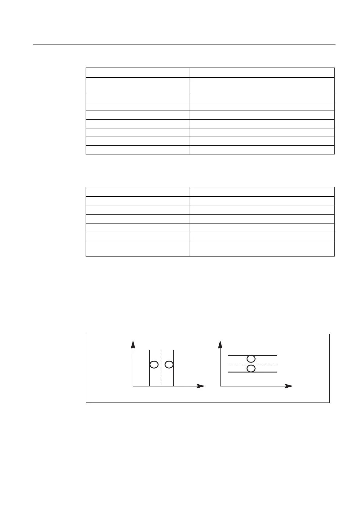
7.5.3.5 Measurement of a groove (measurement type 12)
Measuring points for determining the position of a groove ($AC_MEAS_TYPE = 12)
A groove is measured by approaching the two outside corners or inner edges. The groove
center can be set to a setpoint position. The component of the approach direction
determines the groove position.
\
\
\
[
\
[
[ [
[
\
Figure 7-8 Groove

 Loading...


