B3: Distributed systems - 840D sl only
2.2 NCU link
Extended Functions
86 Function Manual, 03/2013, 6FC5397-1BP40-3BA1
2.2.1.6 Wiring the NCUs
The numerical sequence of the NCUs within a link group is defined in the NCUs using the
following machine data:
MD12510 $MN_NCU_LINKNO = <NCU number>, with NCU number = 1 ... max. NCU
number
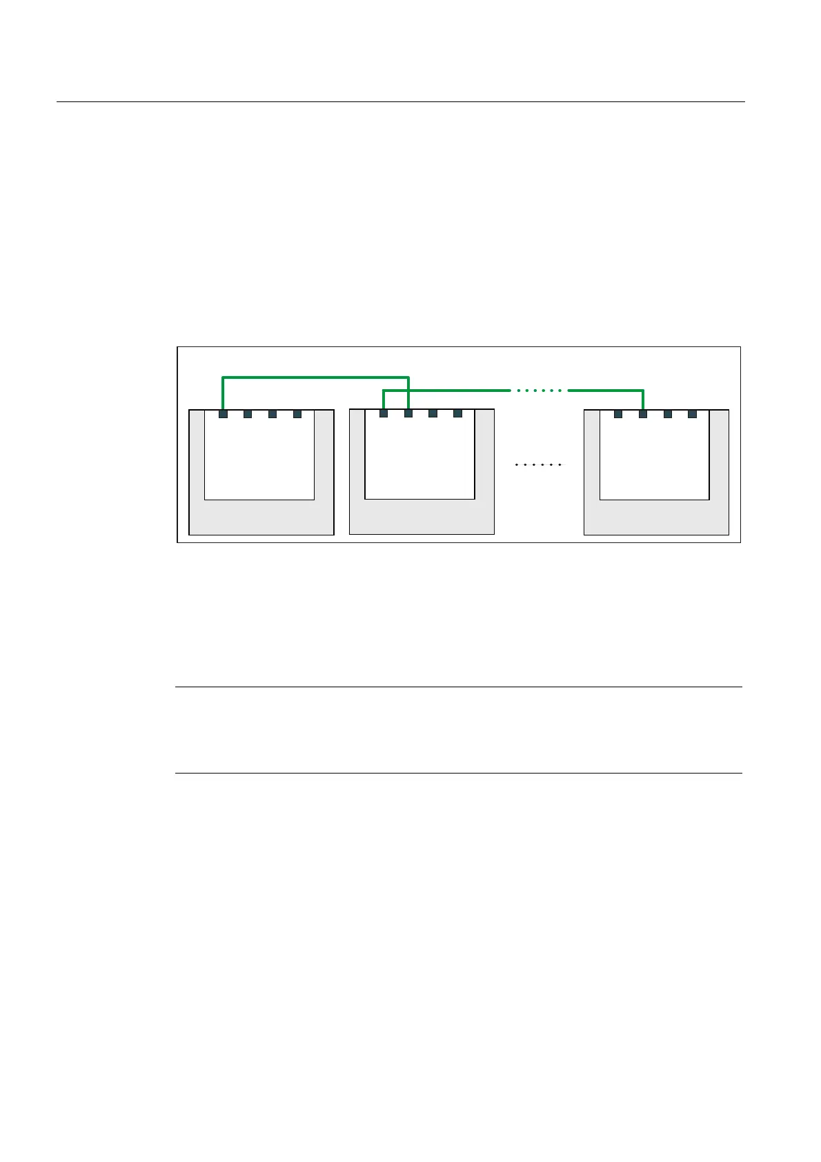
Cabling
Starting from the NCU1, the NCU link modules should be wired up in the NCU number
sequence according to the following schematic: NCU(n), Port 0 → NCU(n+1), Port 1
1&8
/LQNPRGXOH
3RUW
3RUW
3RUW
3RUW
1&8
/LQNPRGXOH
3RUW
3RUW
3RUW
3RUW
1&8
/LQNPRGXOH
3RUW
3RUW
3RUW
3RUW
1&8OLQNYLD352),1(7 1&8OLQNYLD352),1(7
1&8 1&8Q
1&8
Figure 2-6 Wiring schematic, NCU link
2.2.1.7 Activation
The link communication is activated using the following machine data:
MD18780 $MN_ MM_NCU_LINK_MASK, Bit 0 = 1
Note
Activation time
It is recommended to activate the link communication only after complete commissioning of
the entire functionality on all participating NCUs has been done.

 Loading...


