S3: Synchronous spindle
13.1 Brief description
Extended Functions
Function Manual, 03/2013, 6FC5397-1BP40-3BA1
705
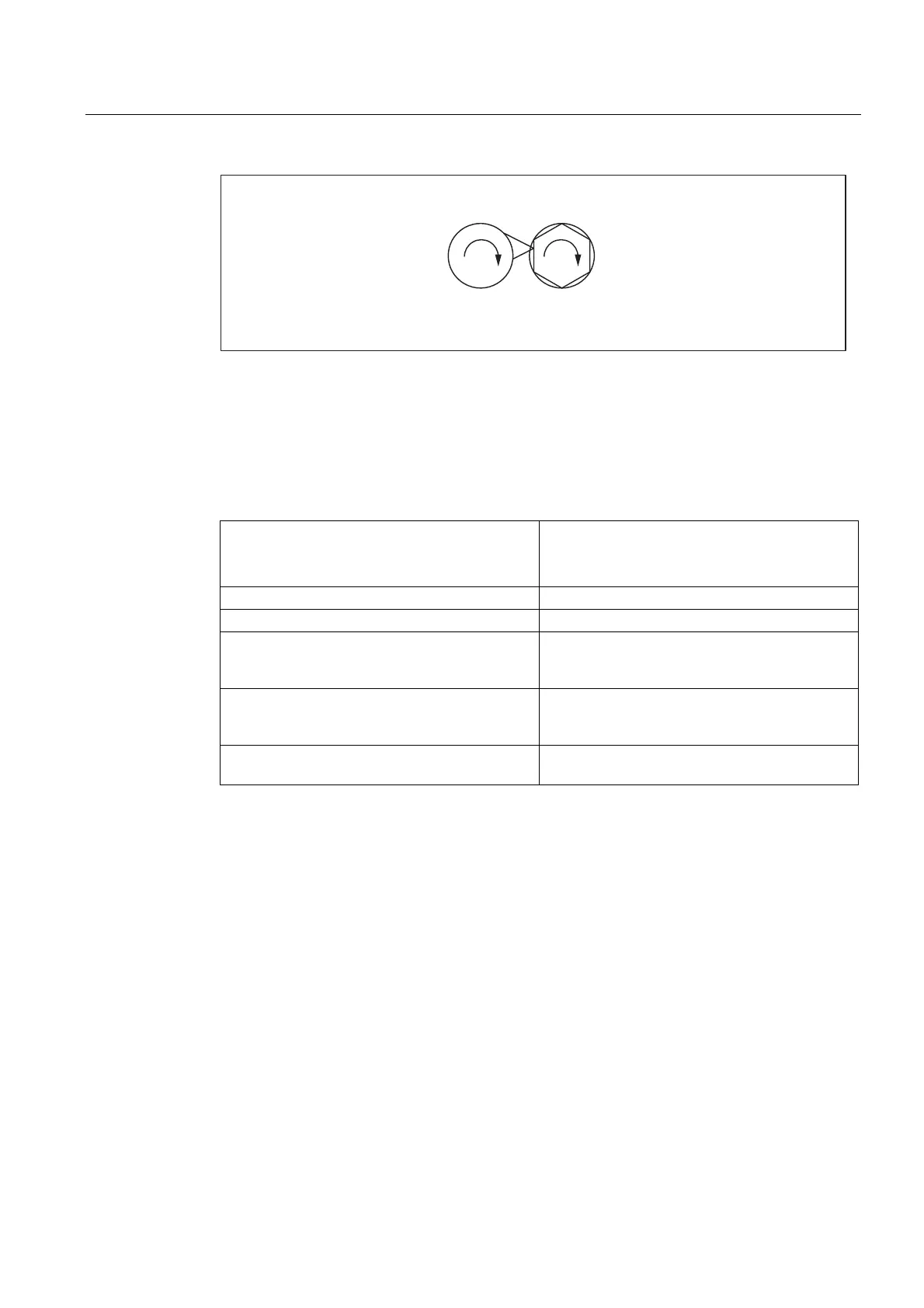
6SLQGOH6SLQGOH
Q Q
Figure 13-2 Synchronous operation: Polygonal turning
13.1.2 Synchronous mode
Description
<axial expression>: can be:
- Axis name
- Spindle name
<axis name>: C (if spindle has the name "C" in axis operation.)
<spindle name>: Sn, SPI(n) where n = spindle number
<Spindle number>: 1, 2, ... according to the spindle number defined
in MD35000
$MA_SPIND_ASSIGN_TO_MACHAX
(FS, LS, offset): LS = Leading Spindle, FS = Following
Spindle,Offset = read programmable offset of
following spindle using system variables
$P_COUP_OFFS[Sn] Programmed position offset of the synchronous
spindle
Synchronous spindle pair
Synchronous operation involves a following spindle (FS) and a leading spindle (LS), referred
to as the synchronous spindle pair. The following spindle imitates the movements of the
leading spindle when a coupling is active (synchronous operation) in accordance with the
defined functional interrelationship.
Synchronous mode
Synchronous mode (also referred to as “Synchronous spindle operation”) is another spindle
operating mode. Before synchronous mode is activated, the following (slave) spindle must
have been switched to position control. Synchronous operation is activated for the following
spindle when the coupling is activated. As soon as the coupling is deactivated, the following
spindle switches back to open-loop control mode.
As soon as synchronous operation is active for the following spindle, the following interface
signal is reported to the PLC:
IS "Synchronous mode" (DB31, ... DBX84.4) = 1.

 Loading...


