M1: Kinematic transformation
6.3 TRACYL cylinder surface transformation (option)
Extended Functions
368 Function Manual, 03/2013, 6FC5397-1BP40-3BA1
Three linear axes (axis configuration 2)
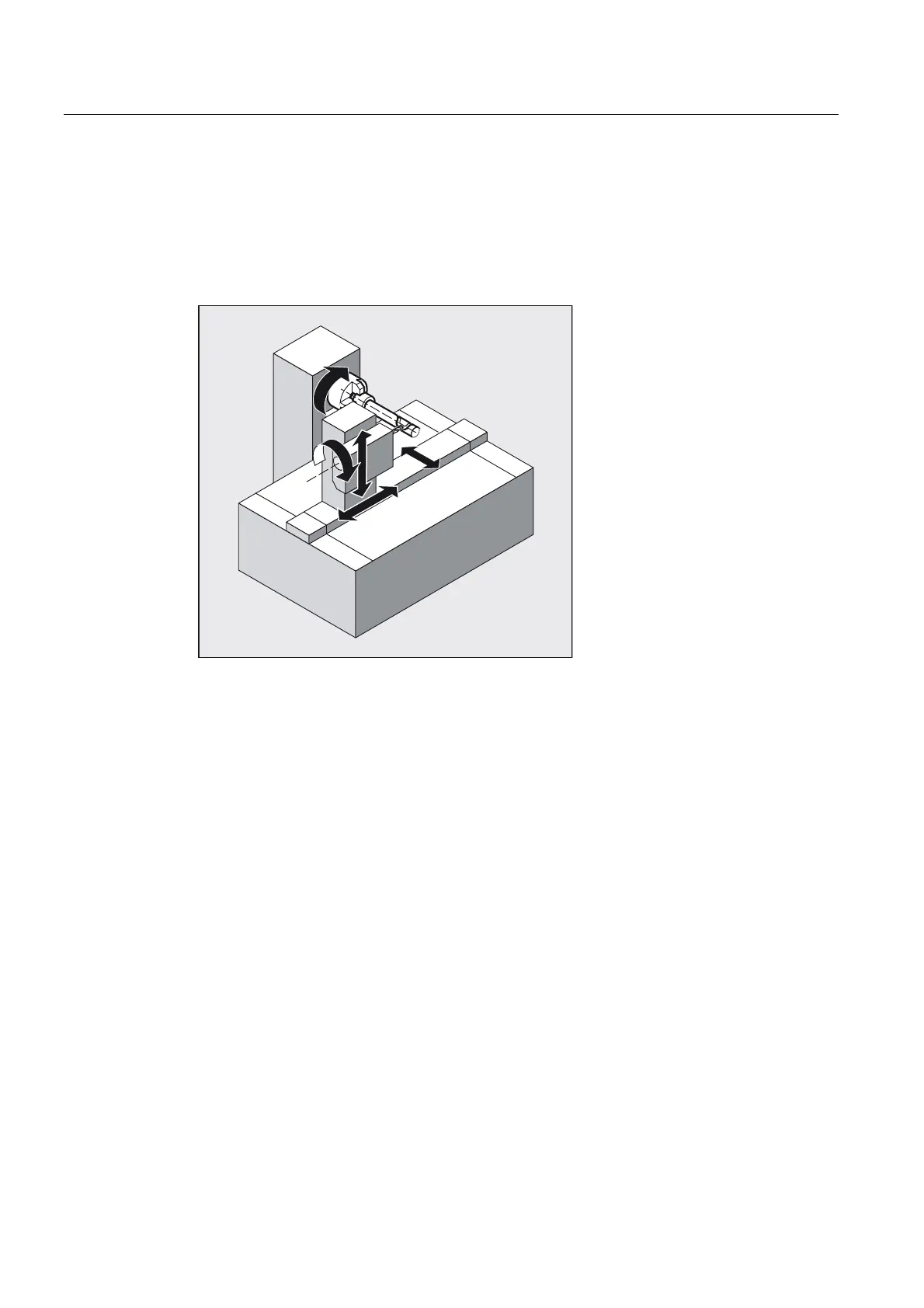
For a machine kinematic with three linear axes (X, Y and Z), grooves of any form can be
generated on the cylinder.
The Y axis oriented perpendicular to the turning center means almost parallel groove edges
can be generated even for groove widths larger than the tool diameter.
<RU&0
=RU=0
<0
$60
;0
XM Infeed axis perpendicular to the turning center
YM Supplementary axis perpendicular to the X-Z plane
ZM Linear axis parallel to the turning center
Y / CM Transformatory Y axis / rotary axis
ASM Working spindle
Figure 6-9 With groove side correction
6.3.1 Preconditions
Maximum number of TRACYL transformations per channel
The following machine data can be used to define transformation data records in a channel:
● $MC_TRAFO_GEOAX_ASSIGN_TAB_<n>
● $MC_TRAFO_TYPE_<n>
● $MC_TRAFO_AXES_IN_<n>
with n = 1, 2, 3, ... max. number of transformation data records
Maximum two data records can be used for the
TRACYL, $MC_TRAFO_TYPE_<n> = 512, 513
or 514 transformation in a channel.

 Loading...


