M1: Kinematic transformation
6.3 TRACYL cylinder surface transformation (option)
Extended Functions
Function Manual, 03/2013, 6FC5397-1BP40-3BA1
367
One or two linear axes (axis configuration 1)
One linear axis
For a machine kinematic with only one linear axis (X), only grooves parallel to the periphery
of the cylinder can be generated.
Two linear axes
For a machine kinematic with two linear axes (X and Z), grooves of any form can be
generated on the cylinder.
The angularity of the groove edges for groove widths larger than the tool diameter:
● Grooves parallel to the circumference ⇒ groove edges parallel to each other
● Grooves parallel to the rotary axis ⇒ groove edges at angle to each other
;0
$60
<RU&0
=RU=0
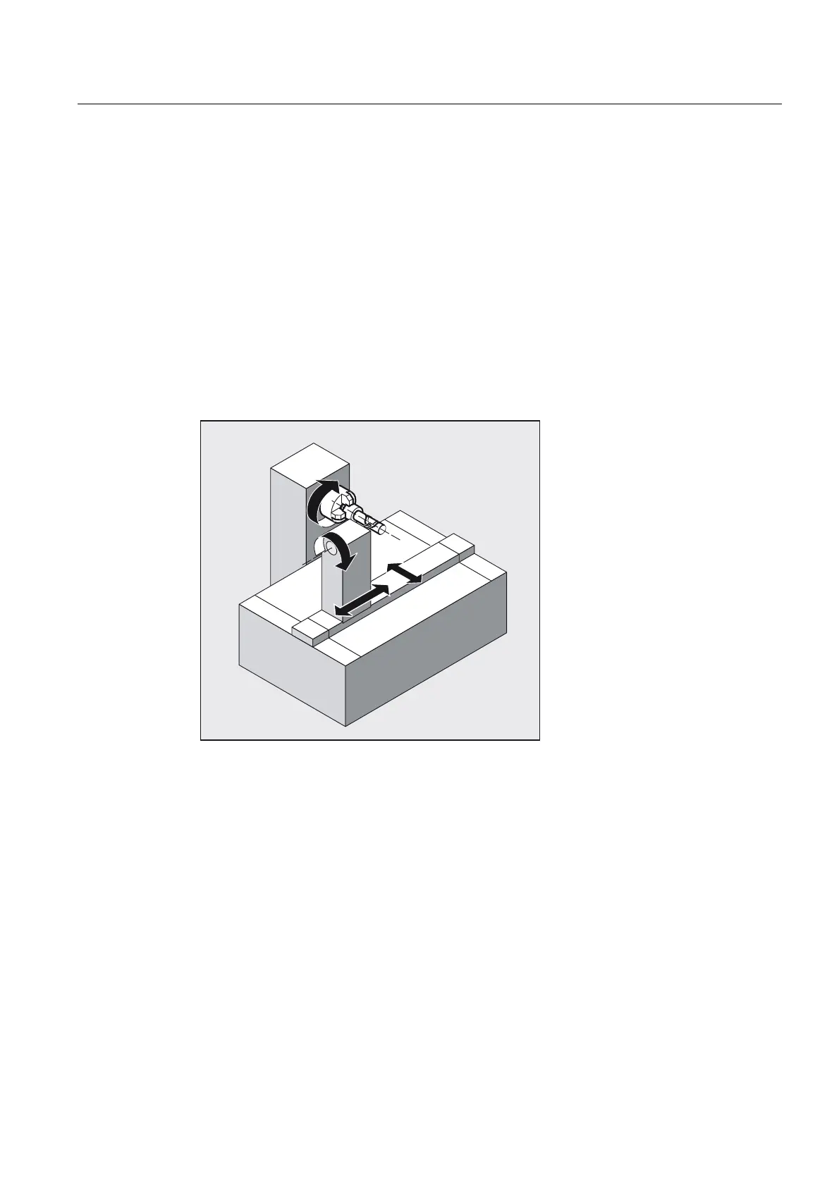
XM Infeed axis perpendicular to the turning center
ZM Linear axis parallel to the turning center
Y / CM Transformatory Y axis / rotary axis
ASM Working spindle
Figure 6-8 Without groove side correction

 Loading...


