K3: Compensations
4.4 Interpolatory compensation
Extended Functions
Function Manual, 03/2013, 6FC5397-1BP40-3BA1
271
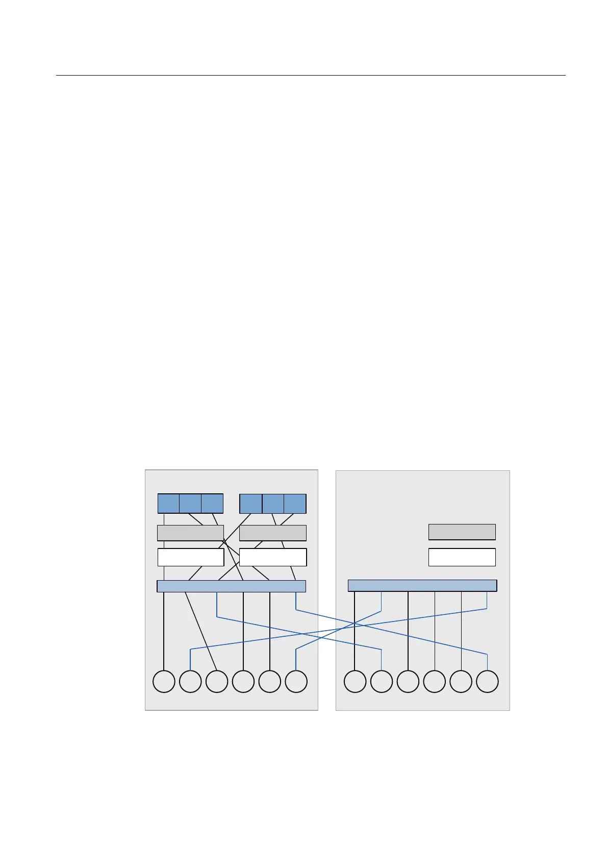
Configuration example
The following figures (Configuration 1, Configuration 2 and Configuration 3) illustrate the axis
configurations of an NCU link that is assembled from two NCUs.
The two channels CHAN-1 and CHAN-2 of NCU-1 are displayed in Configuration 1. Here,
the channel axis names that are defined via the machine data
$MC_AXCONF_CHANAX_NAME_TAB are entered. The channel configuration of the second
NCU is not displayed.
All the axes interpolated by this NCU are compiled in the "Logical NCK machine axis image"
(LAI layer). The assignment between channel and MCS axis layer is done via
$MC_AXCONF_MACHAX_USED.
The assignment between the "Logical NCK machine axis image" and the real axes is
undertaken via the machine data $MN_AXCONF_LOGICMACHAX_TAB. If ones pursues the
connecting line that starts with channel axis ZZ, one ends at Axis AX-2 on NCU-2, i.e. to
traverse the 2nd axis of NCU 2, the following command must be programmed in the 2nd
channel of NCU 1:
"N2040 POS[ZZ]=10 FA[ZZ]=1000"
Configuration 2 and Configuration 3 extend the figure of Configuration 1 by one axis
container (CT1) that is set with machine data $MN_AXCT_AXCONF_ASSIGN_TAB1. The
axis container is an overlapping object, i.e. each axis container exists only once for the
whole NCU cluster.
For NCU 1, the participants in the axis container are channel axes YR and YY; the two
channel axes from NCU2 are not displayed. The container contains the real axes NC1_AX5,
NC1_AX6, NC2_AX1 and NC2_AX2. Container YR connects with NC2_AX1 and YY
connects with NC2_AX2 during the ramp up. In Configuration 3, the container has rotated,
i.e. the connection structure has changed. YR is now connected to NC2_AX2 and YY is
connected to NC1_AX5.
6HUYR9LHZRIWKHUHDOD[HV
/RJLFDOYLHZIRUSDUW
SURJUDPV
1&8
$;$;$; $;$;$;
,QWHUSRODWLRQ
&KDQRQ1&8&KDQRQ1&8
$;$;$; $;$;$;
;5 <5 =5 ;; << ==
,QWHUSRODWLRQ ,QWHUSRODWLRQ
Figure 4-10 Configuration 1: NCU link from channel to real axis

 Loading...


