A4: Digital and analog NCK I/Os for SINUMERIK 840D sl
1.2 Access via PLC
Extended Functions
Function Manual, 03/2013, 6FC5397-1BP40-3BA1
33
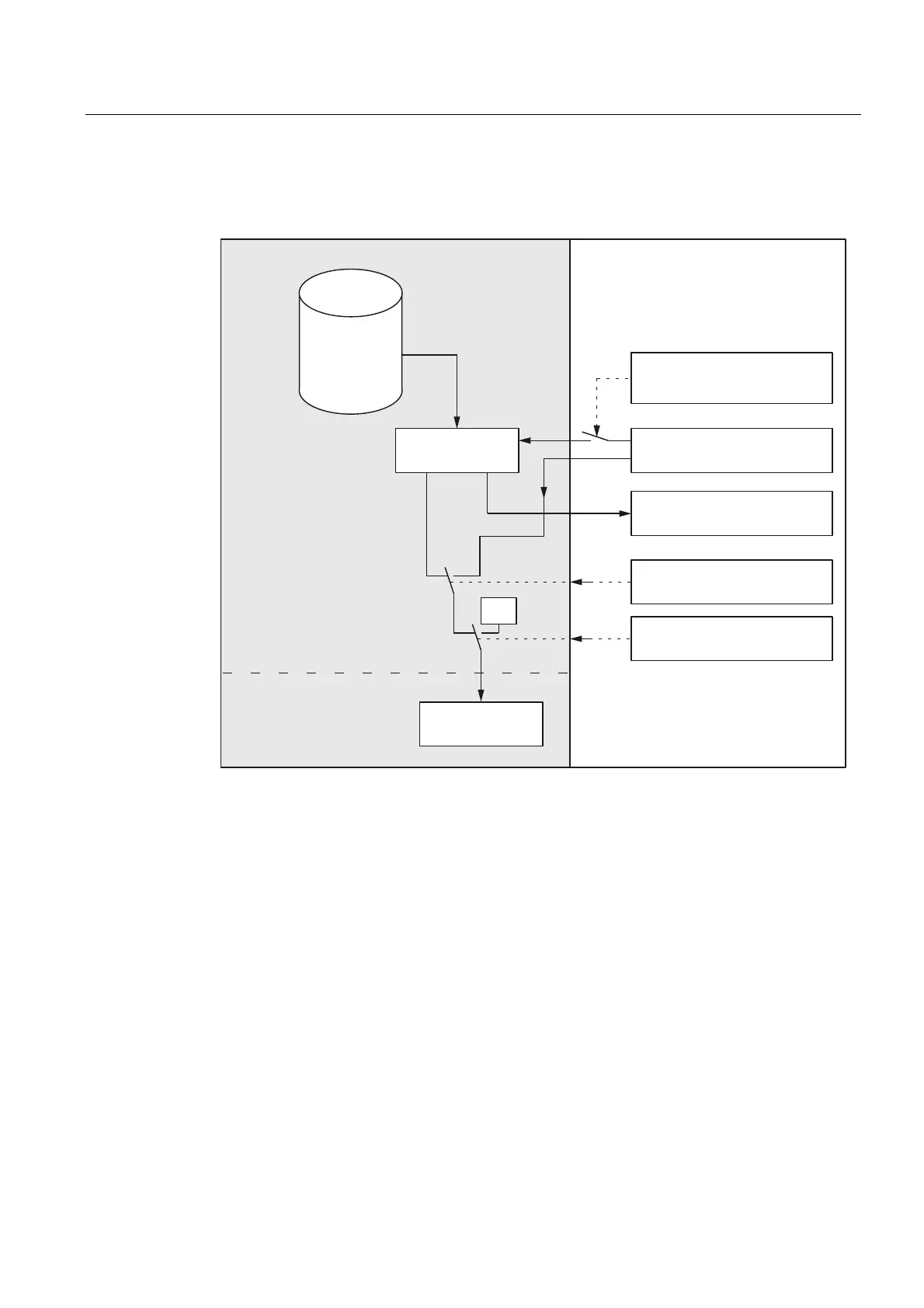
Signal flow
The following figure illustrates the signal flow for the digital NCK outputs.
3/&YDOXH
'LVDEOH
'%'%%RU'%%
6HWWLQJPDVN
'%'%%RU
6HWSRLQW
'%'%%RU'%%
6HWWLQJRIWKHGLJLWDO
RXWSXWLQWKH
SDUWSURJUDP
1&.YDOXH
3/&VHWWLQJYDOXH
'%'%%RU'%%
2YHUZULWHPDVN
'%'%%RU'%%
HGJHFKDQJHൺ
+DUGZDUH
RXWSXW>Q!@
3/&1&.
3DUWSURJUDP
$B287>Q!@
Overwrite mask
Every output that can be set by the NC part program can be overwritten from the PLC using
the overwrite mask. The previous "NCK value" is lost.
The following sequence has to be carried out to overwrite the NCK value from the PLC:
1. The relevant PLC interface output has to be set to the required signal status.
DB10 DBB6 or DBB132 ... (setting value of the digital NCK outputs from the PLC)
2. The "setting value" becomes the new "NCK value" when the overwrite mask for the
relevant output is activated (edge change 0 → 1).
DB10 DBB5 or DBB131 ...
This value remains operative until a new NCK value is programmed (from the PLC or
from the part program).

 Loading...


