M5: Measurement
7.5 Setting zeros, workpiece measuring and tool measuring
Extended Functions
520 Function Manual, 03/2013, 6FC5397-1BP40-3BA1
Different tools in the WCS
6HWSRLQW
6HWSRLQW
6HWSRLQW
6HWSRLQW
7RRORULHQWDWLRQ
$SSURDFKGLUHFWLRQ$SSURDFKGLUHFWLRQ
7RRORULHQWDWLRQ
:&6
%&6
7&3
7&3
:=/ದ
:=/ದ
[
[
[
[
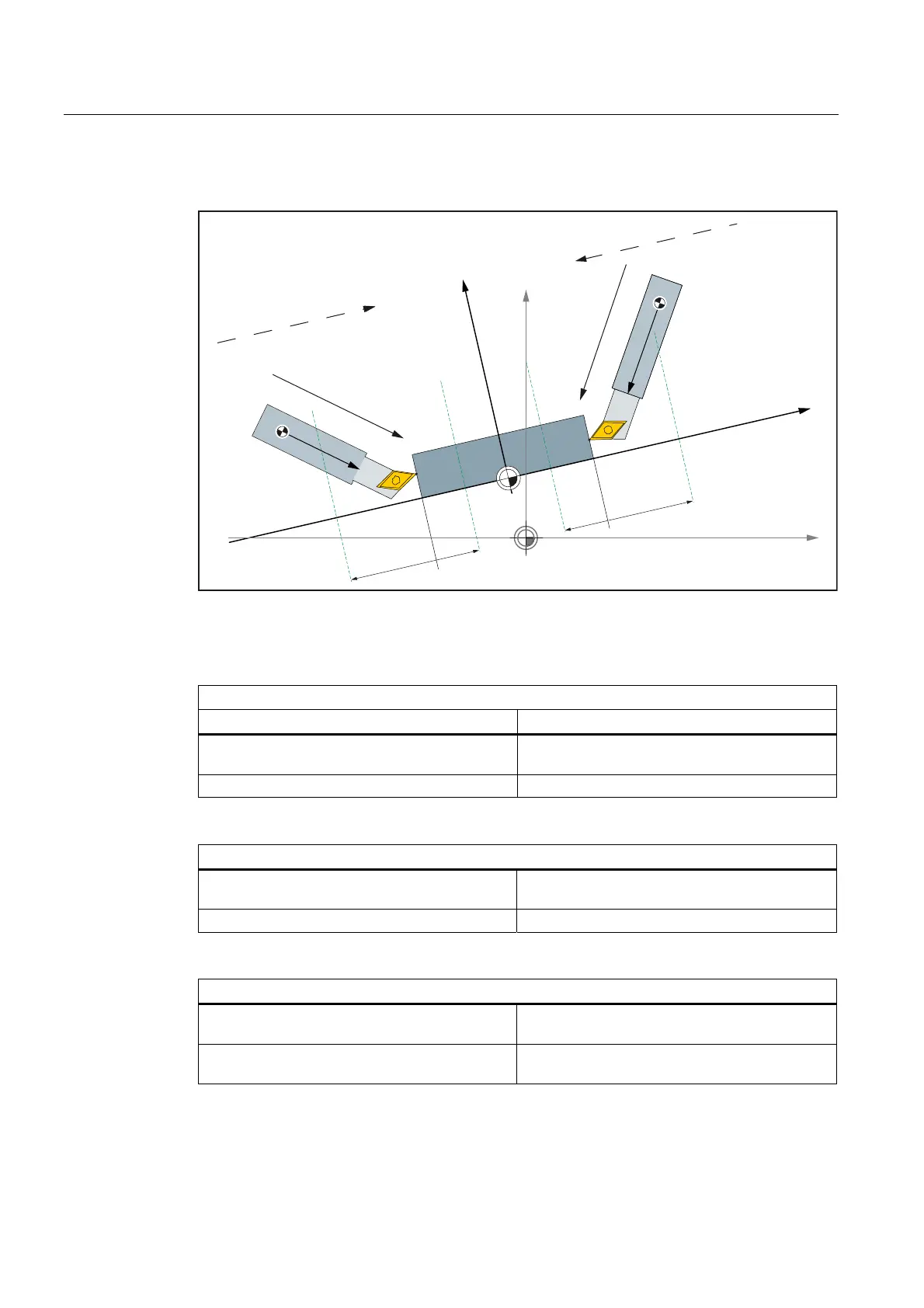
Figure 7-22 Two turning tools each with their own reference point
Settings in the system data:
Left-hand tool: Approach direction +x and tool orientation -y
System variable Meaning
$AC_MEAS_TOOL_MASK = 0x0 All tool lengths are considered
(default setting)
$AC_MEAS_DIR_APPROACH = 0 Approach direction +x
Right-hand tool: Approach direction -x and tool orientation -y
$AC_MEAS_TOOL_MASK = 0x0 All tool lengths are considered
(default setting)
$AC_MEAS_DIR_APPROACH = 1 Approach direction -x
For both tools
$AC_MEAS_Px_COORD = 0 Coordinate system of x-th measuring point =
WCS (default setting)
$AC_MEAS_SET_COORD = 0 Coordinate system of the setpoint =
WCS (default setting)

 Loading...


