M5: Measurement
7.7 Simulated measuring
Extended Functions
526 Function Manual, 03/2013, 6FC5397-1BP40-3BA1
6WDUWSRVLWLRQ
6ZLWFKLQJSRVLWLRQ
(QGSRVLWLRQ
3RVLWLRQRIIVHW
3RVLWLYH
0HDVXULQJEORFN
1HJDWLYH
6ZLWFKLQJVLJQDO
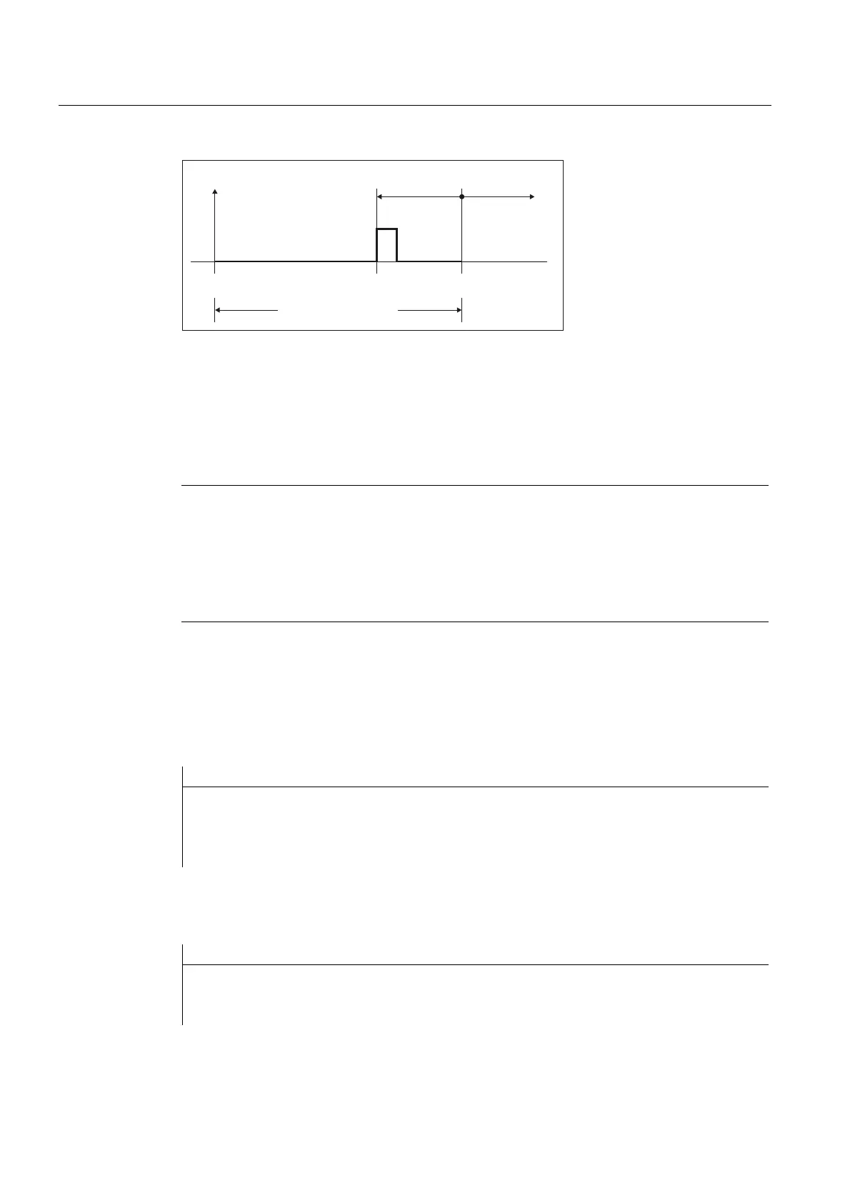
Figure 7-25 Position-dependent switch request
The measured value is the actual value of the axis at the instant in time that the switching
signal programmed in the measuring block occurs (rising / falling edge).
If several axes are programmed in a measuring block, then a dedicated switching position is
obtained for each axis by the position offset that is axially taken into consideration. The
probe signal is generated at the first axial switching position that is reached.
Note
Probe signals
The probe signals are always simultaneously generated for probes 1 and 2.
Negative offset values
The switching position is shifted behind the end position by entering a negative value for the
position offset. In this case, no probe signals are generated.
Examples
The position offset is set to 0.1 mm: MD13231 $MN_MEAS_PROBE_OFFSET = 0.1
Example 1: Channel-specific measuring in 2 axes
Program code Comment
N10 G01 G90
N20 MEAS=1 X100 Y10 F100 ;
;
;
rising edge, probe 1
Switching position[X] = 99.9
Switching position[Y] = 9.9
Example 2: Axial measuring using synchronized action
Program code Comment
N10 G01 G90
N15 WHEN TRUE DO MEASA[X]=(1,1) ; rising edge, probe 1
N20 X10 F100 ; Switching position[X] = 9.9

 Loading...