R2: Rotary axes
12.1 Brief Description
Extended Functions
Function Manual, 03/2013, 6FC5397-1BP40-3BA1
683
Extended addressing (e.g., C2=) or freely configured axis addresses can be used for
additional rotary axes.
Note
Machine data MD20050 $MC_AXCONF_GEOAX_ASSIGN_TAB (assignment of geometry
axis to channel axis) must be adapted to suit the corresponding axis.
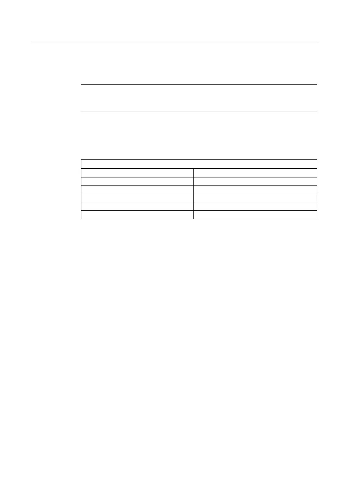
Units of measurement
The following units of measurement apply as standard to inputs and outputs for rotary axes:
Units of measurement for rotary axes
Physical quantity Unit
Angular position Degrees
Programmed angular velocity Degrees/min
MD for angular velocity
1)
rev/min
MD for angular acceleration
1)
rev/sec
2
MD for angular jerk limitation
1)
rev/sec
3
1)
In the case of axis-specific machine data, these units are interpreted by the control as
soon as the axis is declared as a rotary axis. The user can define other units for data
inputs/outputs using machine data.
References:
Function Manual Basic Functions; Velocities, Setpoint/Actual Value Systems, Closed-Loop
Control (G2)
Operating range
The operating range can be defined by means of axis-specific machine and setting data
(software limit switches and working-area limitations). As soon as modulo conversion is
activated for the rotary axis (MD30310 $MA ROT_IS_MODULO = 1), the operating range is
set to unlimited and the software limit switches and working-area limitations become inactive.
Using the following interface signal, software limit switches/working-area limitations can also
be dynamically activated for modulo rotary axes by the PLC (where relevant, initiated from
the part program using M/H functions):
DB31, ... DBX12.4 (modulo-limit enabled)
The feedback signal of the NC is realized using the interface signal:
DB31, ... DBX74.4 (modulo-limit enabled active)

 Loading...


