S3: Synchronous spindle
13.4 Points to note
Extended Functions
Function Manual, 03/2013, 6FC5397-1BP40-3BA1
739
Program code Comment
N05 G4 F1;
N10 COUPDEF(S2,S1,-1) ; Coupling factor -1:1
N11 COUPON(S2,S1) ; Activate coupling, the speed of following spindle S2
; results from the speed of the main spindle S1 and
; the coupling factor
N26 M2=3 S2=100 ; Programming of the speed difference,
; S2 is the following spindle
Application
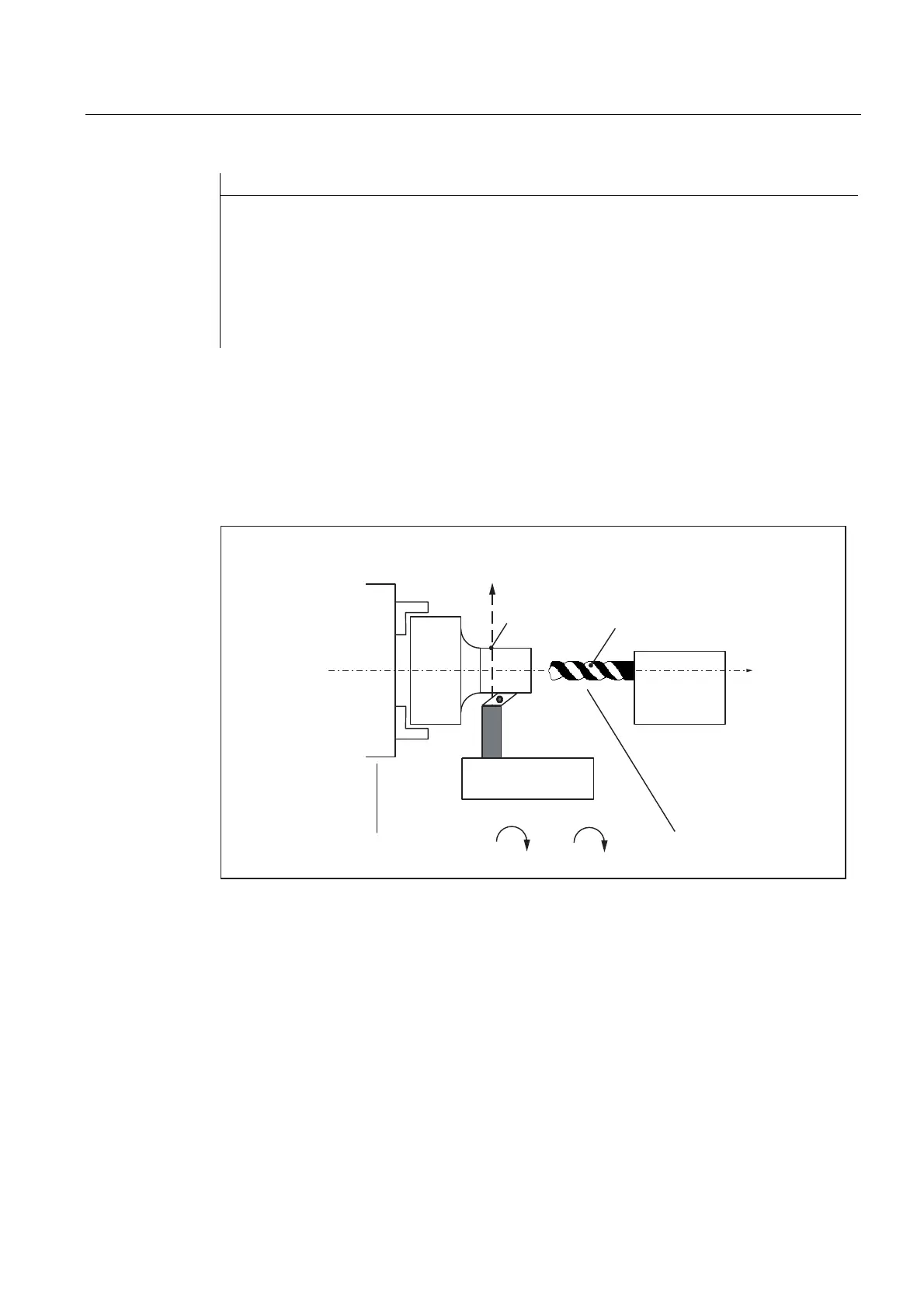
Manufacturing operations with positioned leading spindle and rotating tools require exact
synchronism with the counter spindle which then functions like a following spindle. A turret
rotating about the following spindle allows parts to be machined with different tool types. The
following diagram shows an application in which the tool is positioned parallel to the main
spindle.
6OLGH
7XUQLQJWRRO
;
=
Q
Q
)ROORZLQJVSLQGOH/HDGVSLQGOH
:RUNSLHFH 7RRO
5HYROYHU
0DLQVSLQGOHZLWKZRUNSLHFH
&KXFN
&RXQWHUVSLQGOHZLWKGULYHQ
WRROLQUHYROYHU
Figure 13-5 Application on a single-slide turning machine with turret about Z axis
Requirements
Basic requirements for differential speed programming:
● Synchronous spindle functionality is required.
● The dynamic response of the following spindle must be at least as high as that of the
leading spindle. Otherwise, the system may suffer from reduced quality, for example, rigid
tapping without a compensating chuck G331/G332.

 Loading...


