B3: Distributed systems - 840D sl only
2.1 Brief description
Extended Functions
78 Function Manual, 03/2013, 6FC5397-1BP40-3BA1
1&8
OLQNPRGXOH
1&8
OLQNPRGXOH
1&8OLQNYLD352),1(7
VHWSRLQWWUDQVIHU1&8!1&8VSLQGOH06
8QORDGLQJVWDWLRQ
/RDGLQJVWDWLRQ
0DFKLQLQJVWDWLRQ
0DFKLQLQJVWDWLRQ
6SLQGOH06
6SLQGOH06
6SLQGOH06
5RWDU\D[LV075
6SLQGOH06
'ULYH 'ULYH
1&8
1&8
;
=
;
=
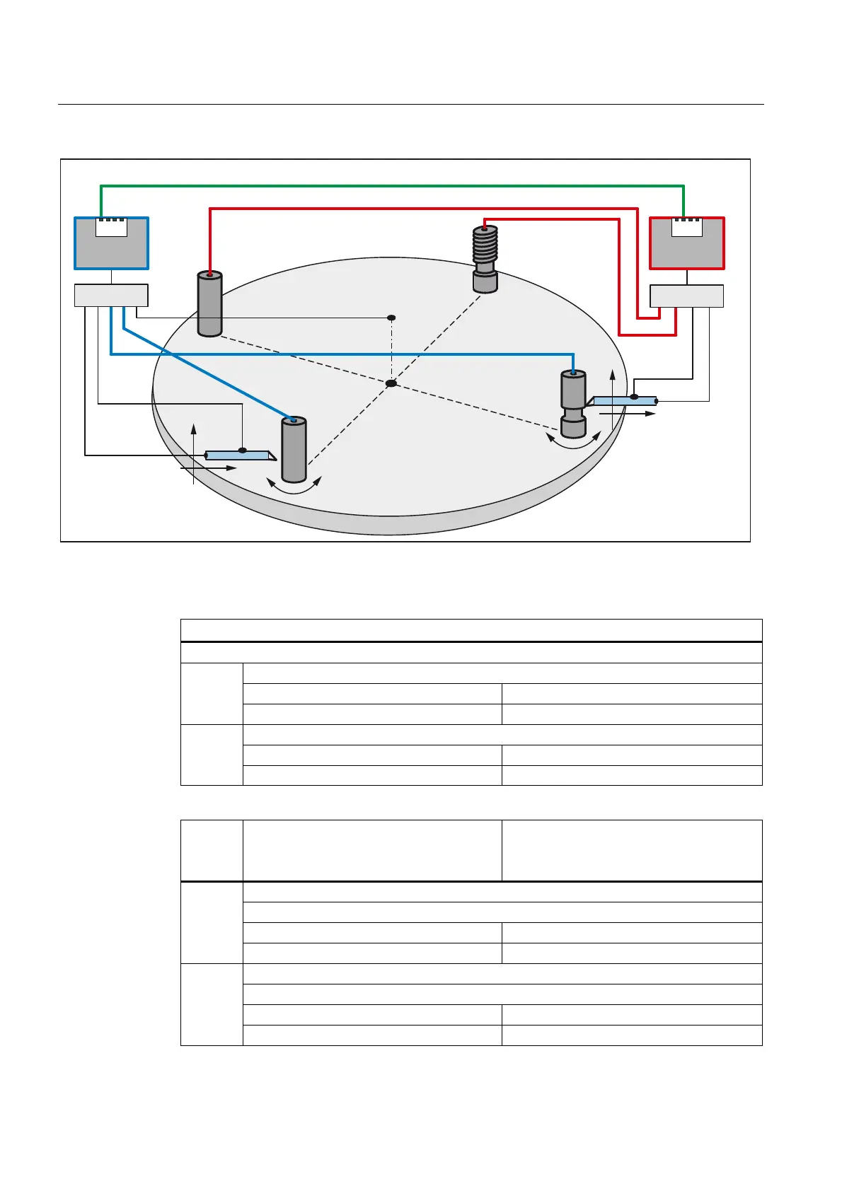
Figure 2-3 Fig. 2: Location after rotation by one position
Parameterization (schematic)
General
Programmed channel axes in the part programs of both NCUs: X, Z, S1
Machine axes defined in the NCU:
Local: X1, Z1
NCU1
Axis container: MS1, MS2
Machine axes defined in the NCU:
Local: X1, Z1
NCU2
Axis container: MS3, MS4
Initial setting
(Fig. 1)
Rotation of the MTR (rotary table) rotary
axis by one position
(Fig. 2)
Machining station 1: X1, Z1, MS2
Diagram showing the channel axes programmed in the part program:
X → X1 and Z → Z1 X → X1 and Z → Z1
NCU1
S1 → MS2 S1 → MS1
Machining station 2: X1, Z1, MS2
Diagram showing the channel axes programmed in the part program:
X → X1 and Z → Z1 X → X1 and Z → Z1
NCU2
S1 → MS3 S1 → MS2 (link axis)

 Loading...


