W3: Tool change
16.8 Examples
Extended Functions
Function Manual, 03/2013, 6FC5397-1BP40-3BA1
799
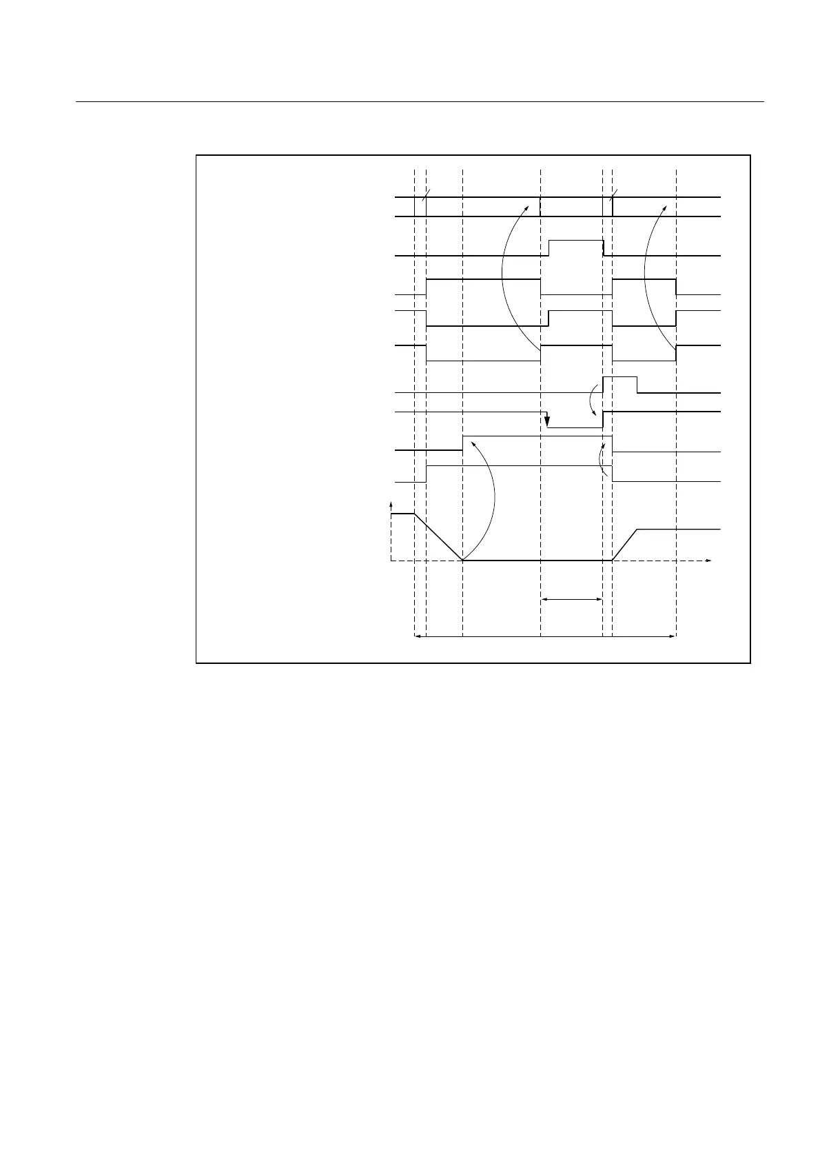
&XUUHQWEORFNQXPEHU
,65HDGHQDEOH
,6([DFWVWRSILQHVSLQGOH
,63RVLWLRQLQJPRGHDFWLYH
6SLQGOHVSHHGLQUSP
3/&QHZWRROORDGHG
,6([DFWVWRSFRDUVHD[LV
,6([DFWVWRSILQHD[LV
,6WUDYHOFRPPDQGD[LV
,6)HHGGLVDEOH
7LPH
722/72
722/7,0(
&8772
&877,0(
WKURXJK0
1
1
1 1
1
W
W
W
W
W
t
1
: Axes stationary.
Spindle rotates.
Start of tool change cycle in
N10.
t
2
: Move axes to tool change point with G75 in N20.
t
3
: Spindle reaches programmed position from block N10.
t
4
: Axes reach exact stop coarse from N20; N30 thus begins:
M06 removes the previous tool from the spindle and loads and clamps the new tool.
t
5
: Tool changer swivels back to original position.
Figure 16-1 Chronological sequence of tool change
Then, in
N1000 of the calling main program:
● The new tool offset can be selected
● the axes can be returned to the contour, or
● the spindle can be accelerated.

 Loading...


