Z2: NC/PLC interface signals
18.1 Digital and analog NCK I/Os (A4)
Extended Functions
Function Manual, 03/2013, 6FC5397-1BP40-3BA1
837
Output 40 Output 39 Output 38 Output 37 Output 36 Output 35 Output 34 Output 33
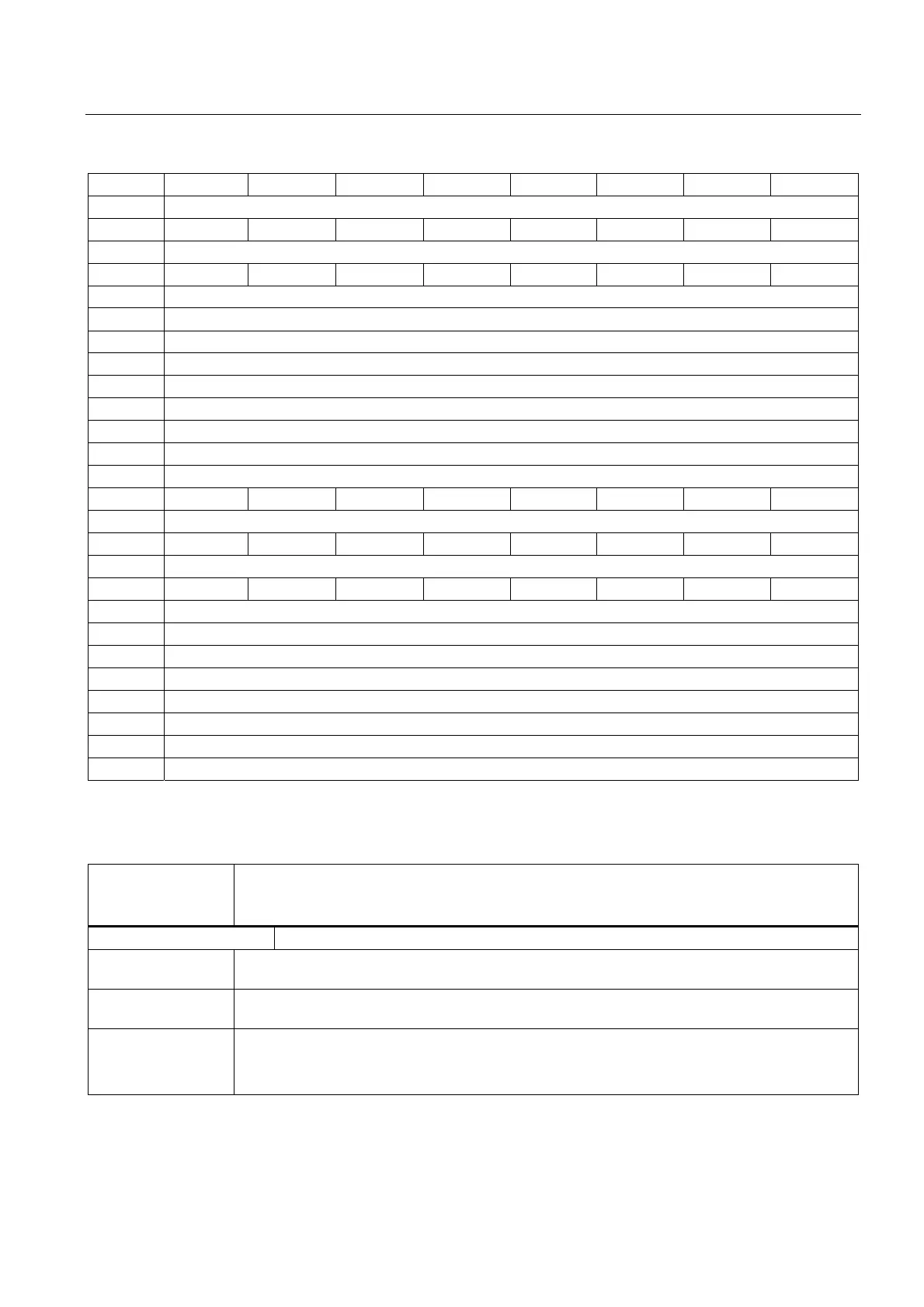
146 Disable analog NCK inputs
Input 8 Input 7 Input 6 Input 5 Input 4 Input 3 Input 2 Input 1
147 Setting screen form for analog NCK inputs
Input 8 Input 7 Input 6 Input 5 Input 4 Input 3 Input 2 Input 1
148, 149 Setting value from PLC for analog input 1 of the NCK
150, 151 Setting value from PLC for analog input 2 of the NCK
152, 153 Setting value from PLC for analog input 3 of the NCK
154, 155 Setting value from PLC for analog input 4 of the NCK
156, 157 Setting value from PLC for analog input 5 of the NCK
158, 159 Setting value from PLC for analog input 6 of the NCK
160, 161 Setting value from PLC for analog input 7 of the NCK
162, 163 Setting value from PLC for analog input 8 of the NCK
166 Overwrite screen form for analog NCK outputs
Output 8 Output 7 Output 6 Output 5 Output 4 Output 3 Output 2 Output 1
167 Setting screen form for analog NCK outputs
Output 8 Output 7 Output 6 Output 5 Output 4 Output 3 Output 2 Output 1
168 Disable analog NCK outputs
Output 8 Output 7 Output 6 Output 5 Output 4 Output 3 Output 2 Output 1
170, 171 Setting value from PLC for analog output 1 of NCK
172, 173 Setting value from PLC for analog output 2 of NCK
174, 175 Setting value from PLC for analog output 3 of NCK
176, 177 Setting value from PLC for analog output 4 of NCK
178, 179 Setting value from PLC for analog output 5 of NCK
180, 181 Setting value from PLC for analog output 6 of NCK
182, 183 Setting value from PLC for analog output 7 of NCK
184, 185 Setting value from PLC for analog output 8 of NCK
Description of signals from PLC to NC
DB10
DBB0, 122, 124, 126,
128
Disable digital NCK inputs
Edge evaluation: No Signal(s) updated: Cyclic
Signal state 1 or
edge change 0 → 1
The digital input of the NCK is disabled by the PLC. It is thus set to "0" in a defined way in the
control.
Signal state 0 or
edge change 1 → 0
The digital input of the NCK is enabled. The signal state applied at the input can now be read
directly in the NC part program.
Corresponding to .... DB10 DBB1 (Setting by PLC of the digital NCK inputs)
DB10 DBB60 (actual value for digital NCK inputs)
MD10350 $MN_FASTIO_DIG_NUM_INPUTS
 Loading...


