Z2: NC/PLC interface signals
18.1 Digital and analog NCK I/Os (A4)
Extended Functions
Function Manual, 03/2013, 6FC5397-1BP40-3BA1
839
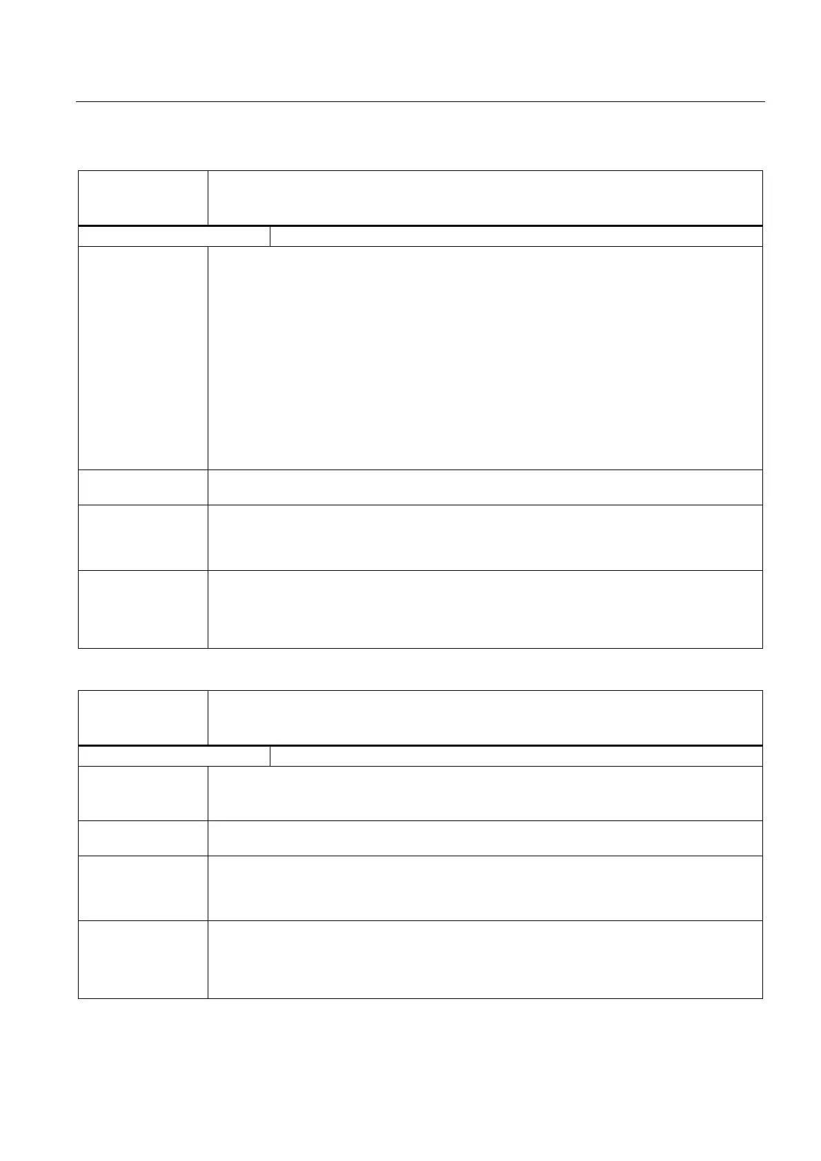
DB10
DBB6, 132, 136, 140,
144
Set value by PLC of the digital NCK outputs
Edge evaluation: No Signal(s) updated: Cyclic
Signal state 1 or
edge change 0 → 1
The signal status for the digital hardware output can be changed by the PLC with the setting value.
There are two possibilities:
• With the "Overwrite screen form":
With signal transition 0 → 1 in the 'overwrite screen form' the PLC overwrites the previous 'NCK
value' with the 'setting value'. This is the new 'NCK value'.
• With the 'setting screen form':
On signal state 1 in the "setting screen form", the "PLC value" is activated. The value used is
the 'setting value'.
With "setting value" "1", signal level 1 is put out at the hardware output. With "0", the output level is
0. The associated voltage values can be found in:
References:
Device Manual, NCU 7x0.3 PN
Signal state 0 or
edge change 1 → 0
As the interface signal is only evaluated by the NCK on signal transition 0 → 1 it must be reset to
"0" again by the PLC user program in the next PLC cycle.
Special cases,
errors, ....
Note:
The PLC interface for the setting value (DB10, DBB6) is used both by the overwrite screen form
(for signal transition 0 → 1) and the setting screen form (for signal state 1). Simultaneous activation
of the two screen forms via the PLC user program must be avoided.
Corresponding to .... DB10 DBB4 (Disable digital NCK outputs)
DB10 DBB5 (Overwrite screen form for digital NCK outputs)
DB10 DBB7 (Setting screen form for digital NCK outputs)
MD10360 $MN_FASTIO_DIG_NUM_OUTPUTS
DB10
DBB7, 133, 137, 141,
145
Setting screen form for digital NCK outputs
Edge evaluation: No Signal(s) updated: Cyclic
Signal state 1 or
edge change 0 → 1
Instead of the NCK value, the PLC value is output at the digital hardware output. The PLC value
must first be deposited in IS "Set value by PLC of the digital NCK outputs".
The current NCK value is not lost.
Signal state 0 or
edge change 1 → 0
The NCK value is output at the digital hardware output.
Special cases,
errors, ....
Note:
The PLC interface for the setting value (DB10, DBB6) is used both by the overwrite screen form
(for signal transition 0 → 1) and the setting screen form (for signal state 1). Simultaneous activation
of the two screen forms via the PLC user program must be avoided.
Corresponding to .... DB10 DBB4 (Disable digital NCK outputs)
DB10 DBB5 (Overwrite screen form for digital NCK outputs)
DB10 DBB6 (Setting value by PLC of digital NCK outputs)
MD10360 $MN_FASTIO_DIG_NUM_OUTPUTS

 Loading...


