Z2: NC/PLC interface signals
18.1 Digital and analog NCK I/Os (A4)
Extended Functions
Function Manual, 03/2013, 6FC5397-1BP40-3BA1
841
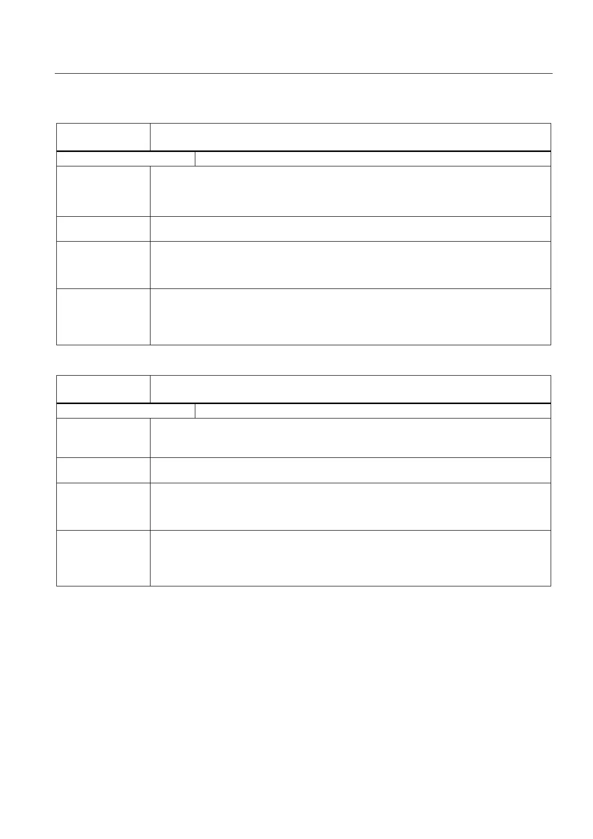
DB10
DBB166
Overwrite screen form for analog NCK outputs
Edge evaluation: No Signal(s) updated: Cyclic
Signal state 1 or
edge change 0 → 1
On signal transition 0 → 1 the previous NCK value is overwritten by the setting value (IS "Setting
value from PLC for analog NCK outputs"). The previous NCK value which, for example, was
directly set by the part program, is lost.
The analog value specified by the PLC setting value forms the new NCK value.
Signal state 0 or
edge change 1 → 0
As the interface signal is only evaluated by the NCK on signal transition 0 → 1 it must be reset to
"0" again by the PLC user program in the next PLC cycle.
Special cases,
errors, ....
Note:
The PLC interface for the setting value is used both by the overwrite screen form (for signal
transition 0 → 1) and the setting screen form (for signal state 1). Simultaneous activation of the two
screen forms must be avoided via the PLC user program.
Corresponding to .... DB10 DBB168 (Disable analog NCK outputs)
DB10 DBB167 (Setting screen form of analog NCK outputs)
DB10 DBB170-185 (Setting by PLC of analog NCK outputs)
MD10310 $MN_FASTIO_ANA_NUM_OUTPUTS
DB10
DBB167
Setting screen form of analog NCK outputs
Edge evaluation: No Signal(s) updated: Cyclic
Signal state 1 or
edge change 0 → 1
Instead of the NCK value, the PLC value is output at the analog hardware output. The PLC value
must first be stored in IS "Setting value from PLC for the analog NCK outputs".
The current NCK value is not lost.
Signal state 0 or
edge change 1 → 0
The NCK value is output at the analog hardware output.
Special cases,
errors, ....
Note:
The PLC interface for the setting value is used both by the overwrite screen form (for signal
transition 0 → 1) and the setting screen form (for signal state 1). Simultaneous activation of the two
screen forms must be avoided via the PLC user program.
Corresponding to .... DB10 DBB168 (Disable analog NCK outputs)
DB10 DBB166 (Overwrite screen form of analog NCK outputs)
DB10 DBB170-185 (Setting by PLC of analog NCK outputs)
MD10310 $MN_FASTIO_ANA_NUM_OUTPUTS

 Loading...


