Z2: NC/PLC interface signals
18.1 Digital and analog NCK I/Os (A4)
Extended Functions
844 Function Manual, 03/2013, 6FC5397-1BP40-3BA1
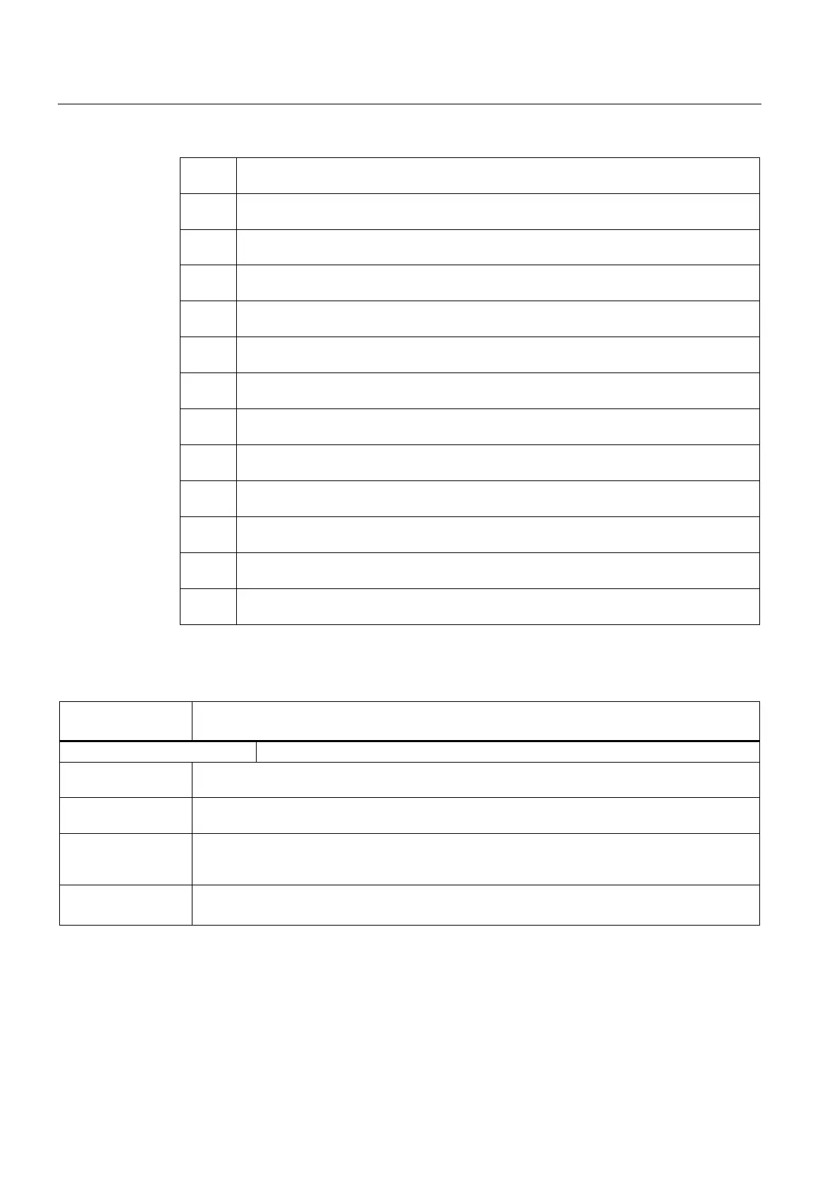
200,
201
Actual value for analog input 4 of NCK
202,
203
Actual value for analog input 5 of NCK
204,
205
Actual value for analog input 6 of NCK
206,
207
Actual value for analog input 7 of NCK
208,
209
Actual value for analog input 8 of NCK
210,
211
Setpoint for analog output 1 of NCK
212,
213
Setpoint for analog output 2 of NCK
214,
215
Setpoint for analog output 3 of NCK
216,
217
Setpoint for analog output 4 of NCK
218,
219
Setpoint for analog output 5 of NCK
220,
221
Setpoint for analog output 6 of NCK
222,
223
Setpoint for analog output 7 of NCK
224,
225
Setpoint for analog output 8 of NCK
Description of signals from NC to PLC
DB10
DBB60, 186 - 189
Actual value for digital NCK inputs
Edge evaluation: No Signal(s) updated: Cyclic
Signal state 1 or
edge change 0 → 1
Signal level "1" is active at the digital hardware input of the NCK.
Signal state 0 or
edge change 1 → 0
Signal level "0" is active at the digital hardware input of the NCK.
Special cases,
errors, ......
The influence of interface signal:
DB10 DBB0 (Disable digital NCK inputs)
is ignored for the actual value.
Corresponding to .... DB10 DBB0 (Disable digital NCK inputs)
MD10350 $MN_FASTIO_DIG_NUM_INPUTS

 Loading...


