B3: Distributed systems - 840D sl only
2.2 NCU link
Extended Functions
Function Manual, 03/2013, 6FC5397-1BP40-3BA1
95
&KDQQHO
/RJPDFKLQHD[LVLPDJH
0'
01B$;&21)B/2*,&B0$&+$;B7$%
0DFKLQHD[HV
0'
01B$;&21)B0$&+$;B1$0(B7$%
&KDQQHOD[HV
0'
0&B$;&21)B&+$1$;B1$0(B7$%
/RFDOD[LV
1&8OLQN
/LQND[LV
'ULYH
'ULYH
1*)
1;=
1&8 1&8
;
=
;
0$
$;
0$
$;
1&B$;
$;
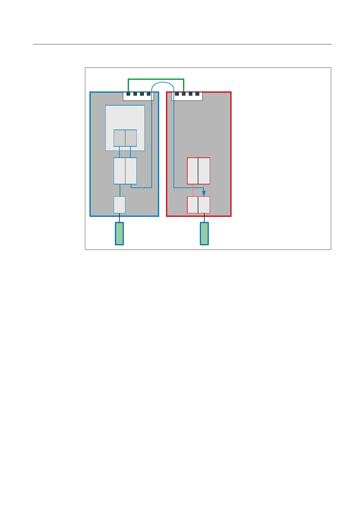
Figure 2-9 Link axes
Requirement
The use of link axes requires a link communication defined in accordance with "Section Link
comm
unication (Page 79)".
Home N
CU
The home NCU of a link axis is the NCU on which it is physically connected as machine axis.
The position control and the exchange of axial NC/PLC interface signals of a link axis always
occurs on the home NCU. The generation of the setpoint can in principle be performed on
any NCU of the link group.
In the above figure:
● NCU1: Home NCU of machine axis MA1
● NCU2: Home NCU of machine axis MA2

 Loading...


