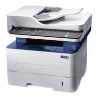
WorkCentre 3210/3220 Multifunction Printer Service Manual 10-7
Wiring
Plug/Jack Locators
The Plug/Jack Locator diagrams show the P/J locations within the printer. Use
these illustrations to locate connections called out in the Troubleshooting
procedures presented in Sections 3, 4, and 5.
1. Locate the P/J connector designator in the first column of the table.
2. With this information, go to the map listed in the second column.
3. Use the coordinates to locate the connection indicated on the map with its
P/J designation number.
4. The Description column provides a brief description of each connection.
Main Controller Board Plug/Jack Designators and Locator
P/J Map Coordinates Description
CN2 5 B-139 Main Fan
CN3 5 I-136 Platen Motor
CN4 5 G-135 Fax Board
CN5 5 I-138 ADF
CN6 5 J-137 USB Port
CN7 5 E-134 Laser Unit
CN8 5 I-135 UI Assembly (Control Panel)
CN9 5 C-133 Laser Unit Fan and Laser Unit interlock switch
CN10 5 B-136 HVPS
CN11 5 H-143 Power Supply Fan
CN12 5 D-143 Out Bin Full Sensor
CN13 5 I-141 Ethernet Port
CN15 5 H-134 Front USB Port
CN16 5 B-140 Power Supply
CN17 5 C-134 Fuser Thermistor, Exit Sensor
CN18 5 B-137 Paper Empty, Registration / Duplex, and Feed Sensor
CN19 5 I-142 Option Tray
CN20 5 B-138 Print Cartridge CRUM
CN21 5 F-143 Drive Unit, Pick Up Solenoid, Registration Clutch
CN22 5 G-133 Platen Assembly
CN25 5 E-138 DIMM
 Loading...


