2-30 WorkCentre 3210/3220 Multifunction Printer Service Manual
Theory of Operation
■ Two 16-byte FIFO data buffers for burst data transfer with extension up to
255 bytes
■ V.21 Channel 1 Flag detect
■ V.21 Channel 1 Flag detect
■ +3.3 V only operation
■ Power Consumption: -264 mW (normal mode)
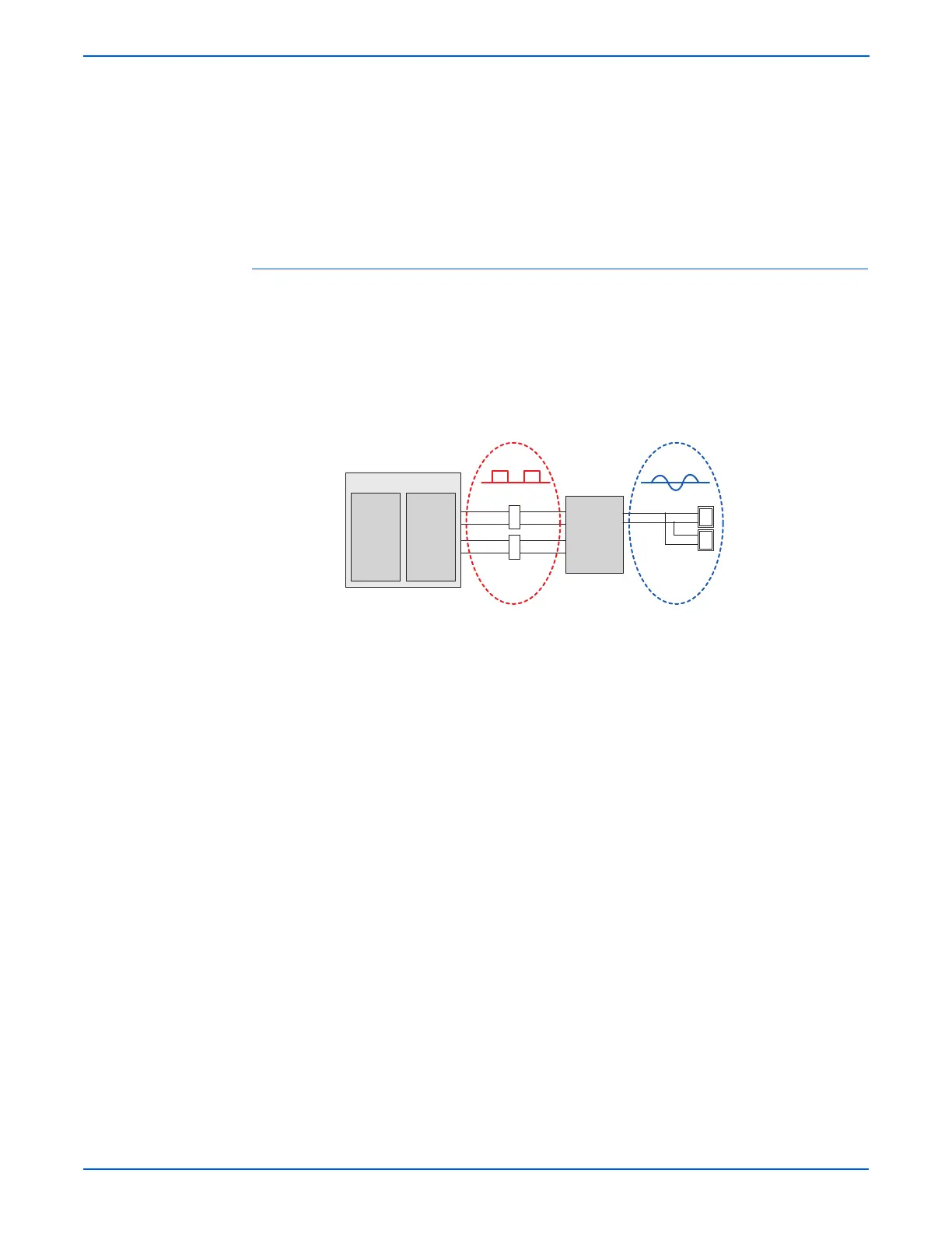
Signal Transition of DAA Solution
Line Interface Signal of Tel Line and LSD is Analog Signal.
There is A/D, D/A Converter in LSD, so analog signal from Tel Line is
converted in digital through A/D converter in DAA and transfer to SSD by DIB
capacitor. The digital signal from SSD is converted to analog by D/A converter
in the DAA and transfer to Tel Line.
The Transformer transfers the Clock signal from SSD to LSD. The clock
frequency is 4.032MHz. The LSD full wave rectifies Clock to use as inner
power supply and Main Clock for DIB Protocol Sync between LSD and SSD.
The Transformer transfers Clock by separating primary and secondary, and
amplifies Clock Level to LSD by Coil Turns Ratio 1:1.16.
Clock is supplied by transformer from SSD to LSD, and there is PWROUT to
adjust output impedance of Clock. Out Driver is inside SSD and CLKSHIGH
resistor to adjust duty of HLPWR resistor and Clock. Clock from SSD to LSD
has differential structure of 180 phase difference for noise robustness.
DIB Data transfers data from SSD to LSD by the transformer, and also
transfers specific data from LSD to SSD.
After transferring data from SSD, RSP is transferred and LSD recognizes RSP
and changes LSD to output driver transfer data to SSD. DIB Data forms SSD
to LSD by the transformer has differential structure of 180 phase difference
between DIBP and DIBN for noise robustness.
G
s3210mfp-144
CX86710(SFX336)
DSP
SSD
System
Side
Device
Transformer
Transformer
CX20493
LSD
Line
Side
Device
Tel Line
Ext Line
1 0 1
Digital
Analog