Network setpoint
In order to set the network generally as a standard setpoint source, select "Network [5]" in
0x2860:001 (P201.01). If another standard setpoint source is set, a change-over to the network
setpoint via the used network control is possible in case the network control is activated:
Network control word
Change-over to network setpoint
0x4008:001 (P590.01)
Assign the functionActivate network setpoint [17]" to the bit that is to be used for activating the network
setpoint.
The functions that are to be triggered via bits 0 ... 15 of the NetWordIN1 data word are defined in
0x400E:
001 (P505.01) ... 0x400E:016 (P505.16).
Standard setpoint source selected in 0x2860:001 (P201.01).
AC drive control word
0x400B:001 (P592.01)
The network setpoint is activated via bit 6 of the AC Drive control word:
Standard setpoint source selected in 0x2860:001 (P201.01).
0x6040
In case of control via device profile CiA 402:
In the operating mode "CiA: Velocity mode [2]", the setpoint speed defined via the "Target velocity"
0x6042 (P781.00) parameter is used.
Device profile CiA 402
299
A change-over to an alternative setpoint source via the CiA 402 Controlword is not possible.
If a bipolar network setpoint is specified for the operating mode "MS: Velocity mode" (e.g. via the
mappable parameter 0x400B:006 (P592.06)), the direction of rotation cannot be controlled via the
network control word. The direction of rotation is determined by the sign of the setpoint.
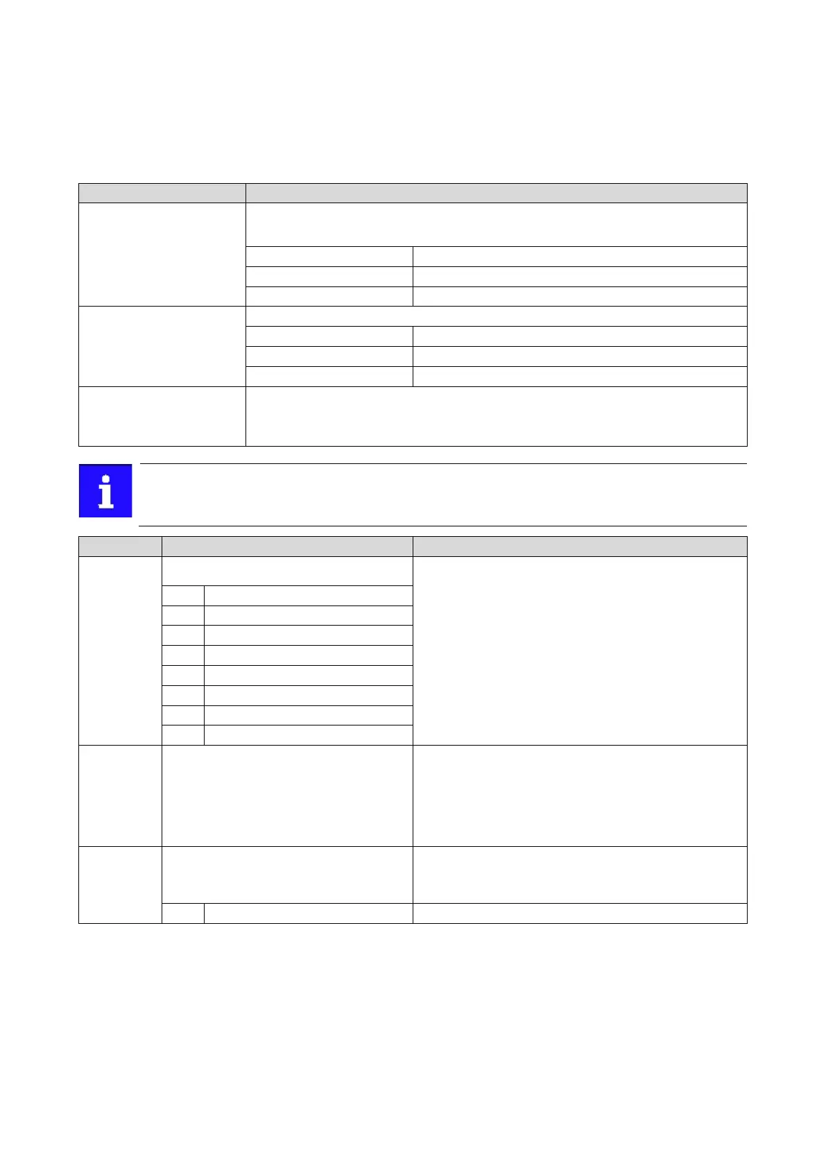
Name / value range / [default setting]
(P500.01)
Module ID: Active module ID Module ID: Active
module ID) R
ead only
Display of the network options currently configured in the inverter.
With the help of this module ID, the keypad only shows the
communi
cation parameters relevant to the respective network.
Note!
When switched on, the inverter checks whether the parameter settings
saved in the memory module match the inverter hardware and
firmware. In case of an incompatibility, a corresponding error message
is output. For details see chapter "Data handling" (section "Hardware
and firmware updates/downgrades").
86
71
EtherNet/IP (from version 02.00)
(from version 02.00)
(from version 02.00)
87
Modbus
(P500.02)
Module ID: Module ID connected
(Module ID: Module ID conn.)
Read only
For the meaning of the display see parameter
0x231F:001 (P500.01).
168
Display of the network option currently available in the inverter.
Note!
When switched on, the inverter checks whether the parameter settings
saved in the memory module match the inverter hardware and
firmware. In case of an incompatibility, a corresponding error message
is output. For details see chapter "Data handling" (section "Hardware
and firmware updates/downgrades").
86
(P505.01)
NetWordIN1 function: Bit 0
(NetWordIN1 fct.: NetWordIN1.00)
Setting can only be changed if the inverter is
inhibi
ted.
Definition of the function that is to be triggered via bit 0 of the
mappable NetWordIN1 data word.
Trigger bit without any function.