214323 299 Revision A
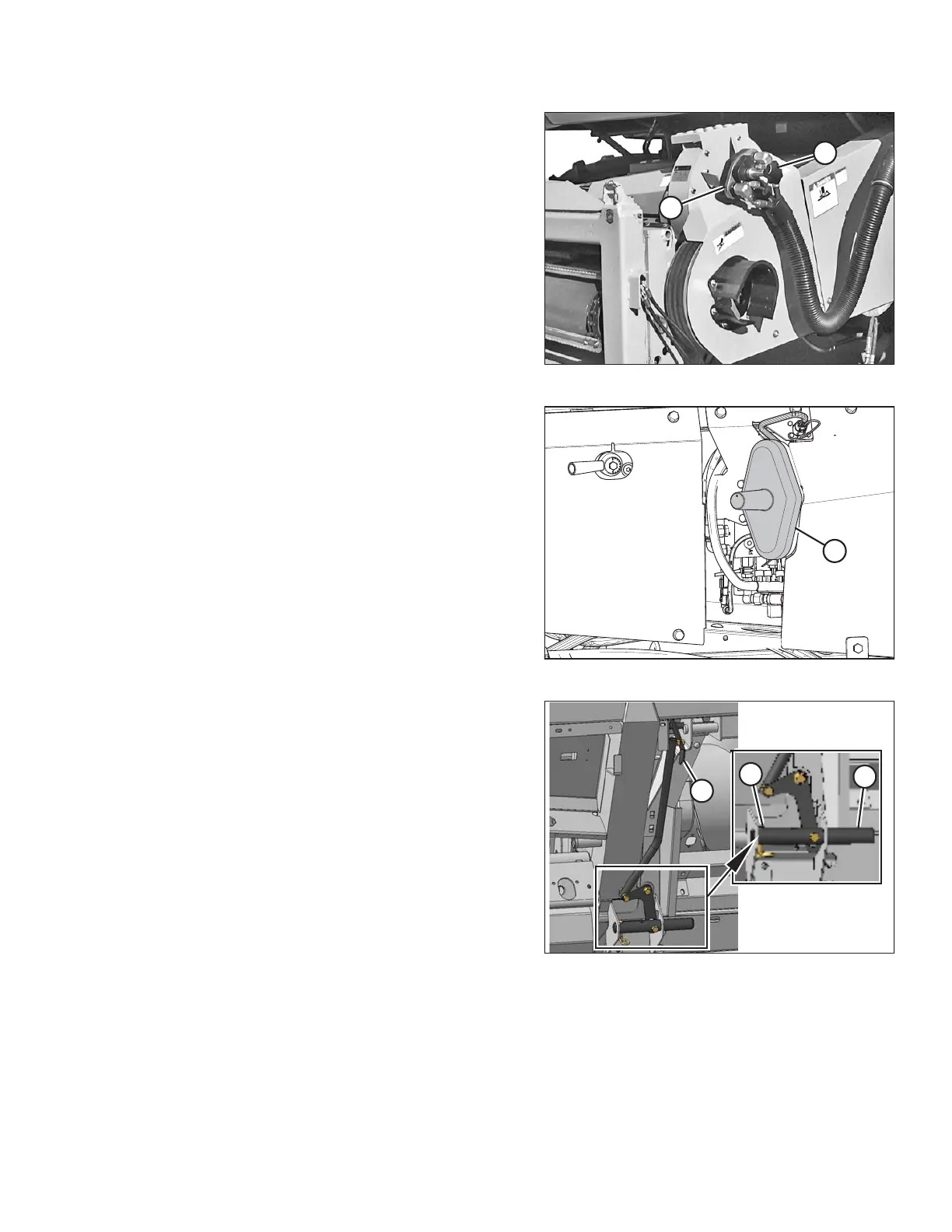
Figure 4.70: Combine Coupler
9. Position coupler (B) onto the combine receptacle, and
turn knob (A) to secure the coupler to the receptacle.
Figure 4.71: Adapter Receptacle Cover
10. Place cover (A) on the adapter receptacle.
Figure 4.72: Feeder House Locks
11. Remove locking pin (A) from CA25 pin (B).
12. Raise handle (C) to disengage CA25 pins (B) from the
feeder house.
13. Replace locking pin (A) in the CA25 pin, and secure
with the hairpin.
HEADER ATTACHMENT/DETACHMENT