214323 303 Revision A
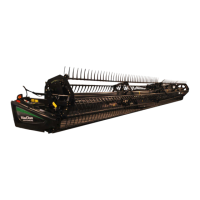
Figure 4.79: Connections
12. Position coupler (A) onto CA25 receptacle, and push
handle (B) to engage pins into receptacle.
13. Push handle (B) to closed position until lock button (C)
snaps out.
14. Remove cover on CA25 electrical receptacle.
15. Remove connector (D) from combine.
16. Align lugs on connector (D) with slots in CA25
receptacle, and push connector onto receptacle. Turn
collar on connector to lock it in place.
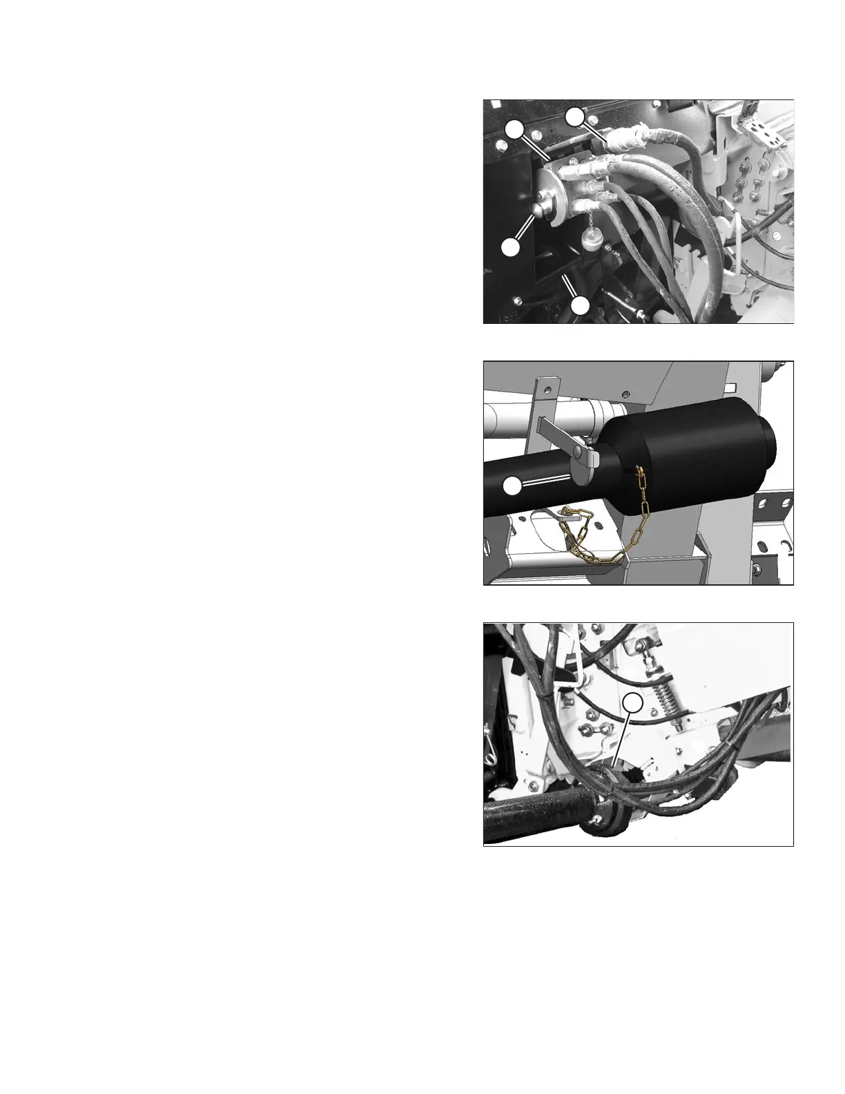
Figure 4.80: Driveline
17. Rotate disc (A) on adapter driveline storage hook, and
remove driveline from hook.
Figure 4.81: Driveline and Output Shaft
18. Pull back collar on end of driveline, and push driveline
onto combine output shaft (A) until collar locks.
HEADER ATTACHMENT/DETACHMENT