214323 311 Revision A
Figure 4.96: Float Locked
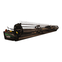
6. Engage both float locks by lifting each lock lever (A)
upwards until it latches into the lock position.
NOTE:
Stabilizer/Slow Speed Transport wheels can be used to
support the header.
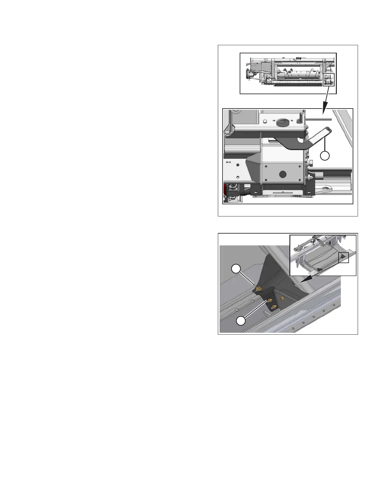
Figure 4.97: Fillers
7. Remove the two hex head bolts (A) attaching filler (B) to
the transition pan at the front corners.
8. Fold back filler (B) to access the latch.
HEADER ATTACHMENT/DETACHMENT