215916 186 Revision A
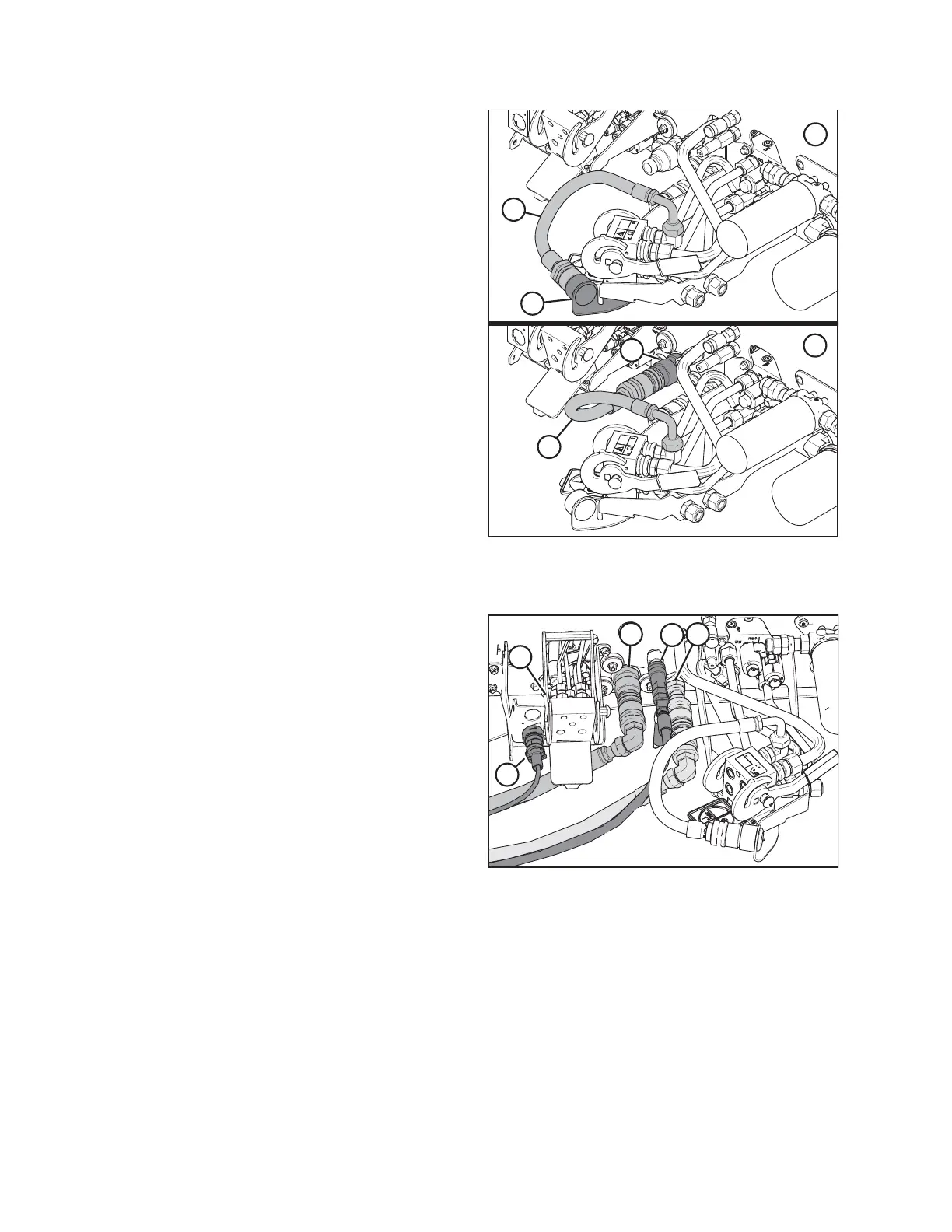
Figure 4.162: Knife Pressure Hose Positions
1 - Knife Pressure Hose in Storage Position – Rotary Configuration
2 - Hose to Knife Pressure Receptacle – Auger/Draper Configuration
5. If you are switching from an auger/draper header to a
rotary header: Disconnect hose (A) from knife pressure
receptacle (C) on the frame and move it to storage
location (B).
Figure 4.163: Hydraulic and Electrical Connections
6. Attach the couplers to the receptacles on the windrower as
follows:
a. Connect the pressure hose female coupler to
receptacle (A)
b. Connect the return hose male coupler to receptacle (B)
c. Connect the case drain hose coupler to receptacle (C)
d. Connect the electrical harness to receptacle (D)
IMPORTANT:
The hydraulic hoses should have enough slack to pass by
multicoupler (E) without coming into contact with it. This
will protect the hoses from rubbing against the multicoupler
and becoming damaged. You can increase slack in the hoses
by loosening and adjusting the hose holder on the front
windrower leg, and pulling the hoses backward toward the windrower.
OPERATION