215916 187 Revision A
Figure 4.164: Left Cab-Forward Platform
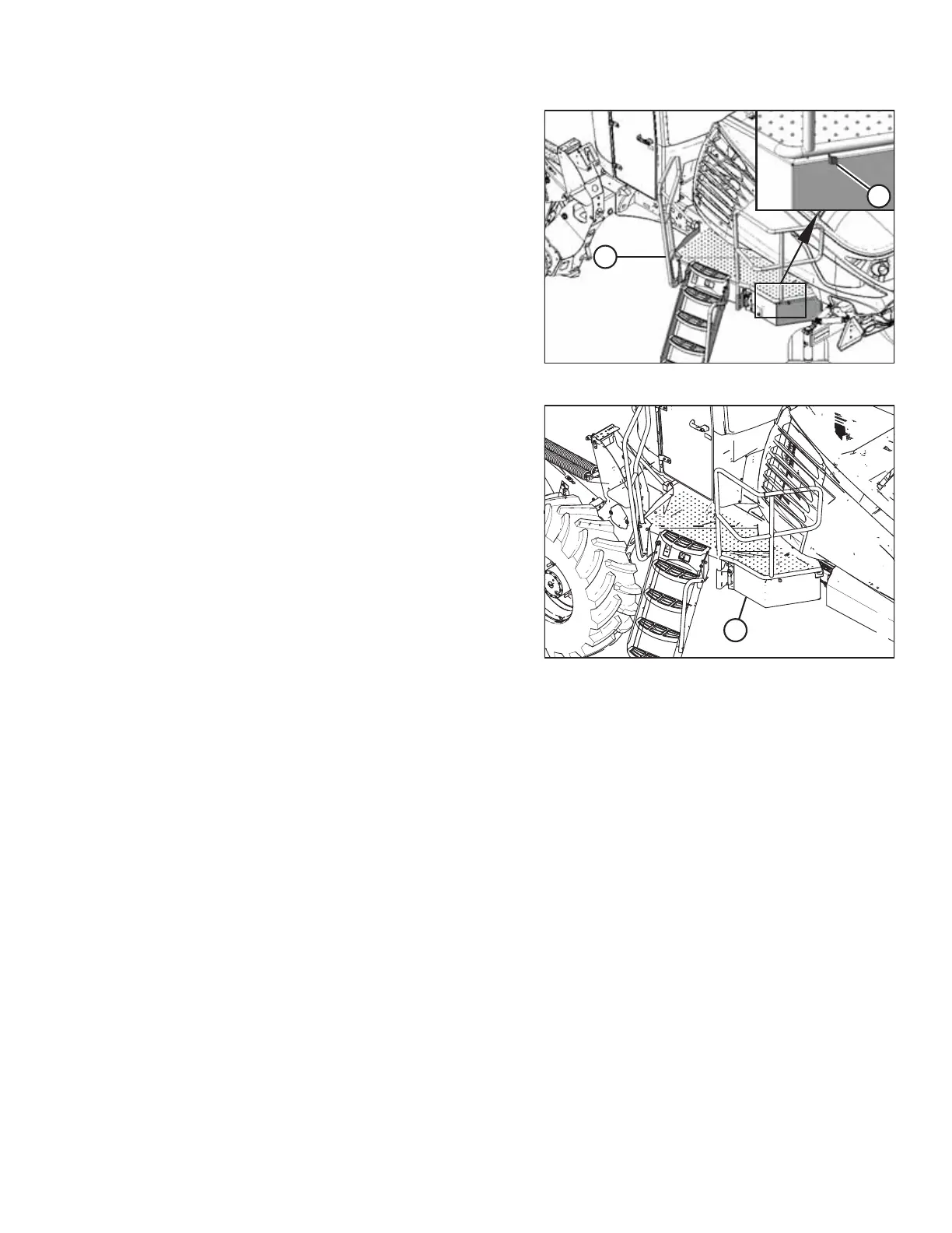
7. Push latch (A) to unlock platform (B).
Figure 4.165: Left Cab-Forward Platform
8. Pull platform (A) towards the cab until it stops and the latch
is engaged.
9. If necessary, calibrate both the knife drive and header position sensors on the windrower. Calibrate both the knife
drive and header position sensors whenever you are:
• Attaching the header to the windrower for the first time
• Changing the speed sensor or hydraulic drive motor on the header
• Changing the header drive pump associated with the knife drive, Harvest Performance Tracker (HPT), or the master
controller on the windrower
For instructions, refer to .
Connecting R113 Rotary Disc Header Hydraulics and Electrical to Windrower
The procedure for connecting the R113’s hydraulic and electrical systems to the windrower differs depending on the
configuration of the windrower.
IMPORTANT:
Before connecting the hydraulics from an R113 Rotary Disc Header to an M1240 Windrower, first install the M1240 Low
Pressure Case Drain kit (MD #B6698) by following the instructions provided included with the kit.
The procedure for connecting the R113’s hydraulic connections to the windrower depends on the windrower’s
configuration:
• Auger/rotary disc/draper header-ready windrowers are equipped with a set of hydraulic quick couplers which are
compatible with the header drive hoses on the rotary disc header.
OPERATION