215916 188 Revision A
• Rotary disc header-ready windrowers are equipped with hard-plumbed hydraulic connections.
IMPORTANT:
To prevent contamination of the hydraulic system, use a clean rag to remove dirt and moisture from all hydraulic couplers.
NOTE:
The R113 Rotary Disc Header hydraulic bundle includes a complete set of quick couplers that can be installed onto a rotary
disc header-configured windrower.
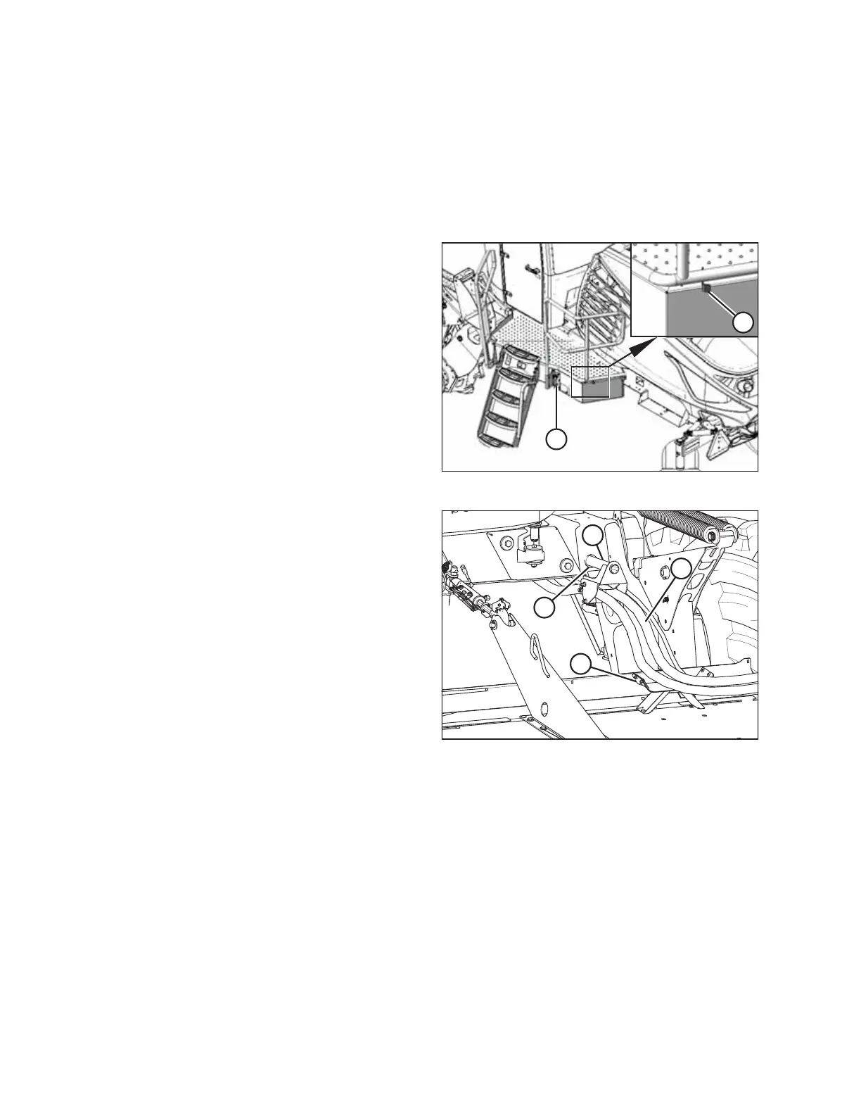
Figure 4.166: Left Cab-Forward Platform
1. Approach platform (A) on the left cab-forward side of the
windrower and ensure the cab door is closed.
2. Push latch (B), and pull platform (A) toward the walking
beam until it stops and the latch engages.
Figure 4.167: R1 Rotary Disc Header Hose Support
Attachment
3. Retrieve hydraulic hoses (A) from the header and route the
hose bundle under the windrower frame.
NOTE:
Adding anti-seize compound to the hose-holder pin will
make future removal easier.
4. Insert pin (B) into hole (C) in the windrower frame and
place the hose bundle onto support (D).
IMPORTANT:
Route the hydraulic hoses as straight as possible, and avoid
rub/wear points that could damage the hoses. The hoses
should have enough slack to pass by the multicoupler
bracket without contacting it. To adjust the slack in the
hose, loosen the clamps below pin (B), adjust the hoses,
then retighten the hose holder.
OPERATION