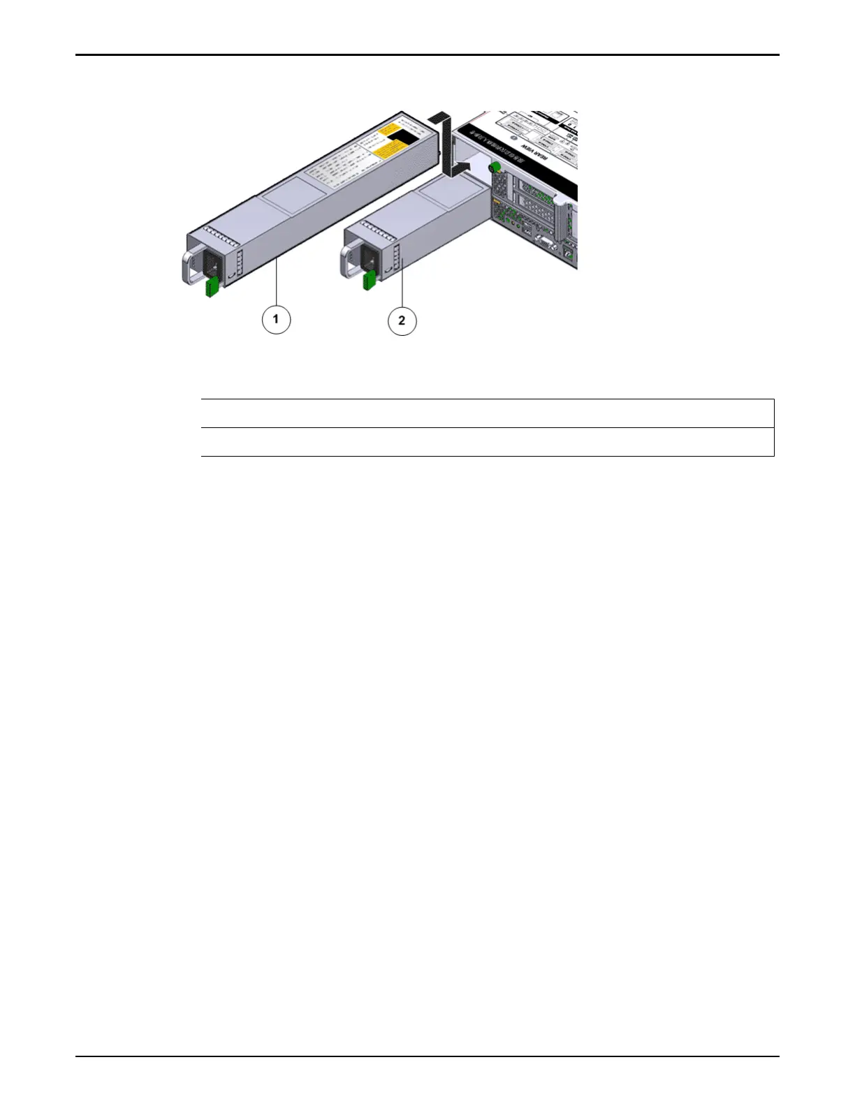
Figure 72: Power supply location
Legend
1 Power supply-1 (PS-1)
2 Power supply-0 (PS-0)
Note: T
o replace a power supply, you can access the faulted power supply from
the back of the Controller module. To access the power supply located in the
boom slot (PS-0), the CMA clip must be disconnected to enable the power
supply to clear the support arm.
Note: Replacing the power supply does not require you to slide the Controller
into the extended rack position and can be performed while the Controller is in
the rack position.
Note: Ensure that the power strain relief strap on the power supply is positioned
correctly such that there is proper clearance and the power supplies can be re-
inserted into the power supply compartment without interference.
Note: Ensure that the power cable is routed correctly and there is no interference
with the Controller chassis.
Important: Do not remove the failed power supply until you have a replacement
power supply to ensure proper airow in the Controller.
Note: For fan replacement, the Replaceable Unit list displays the names of each
fan. Each power supply contains one fan, and each fan module contains two fans.
If a fan fails in a power supply, replace the power supply. If a fan fails in a fan
module, replace the fan module. The following list identies the names of the
fans and the corresponding customer replaceable unit (CRU).
If the following fan fails Replace the following CRU
Fan 0
Power supply 0
Controller Replacement Procedures
103