Legend
1 Power cooling module 2 Opened aachment lever
2 As the power cooling module contacts the Drive Enclosure chassis
midplane, close the aachment lev
er.
To conrm that the power cooling module is properly closed, listen for an
audible click or feel the part engage with the Drive Enclosure chassis
midplane.
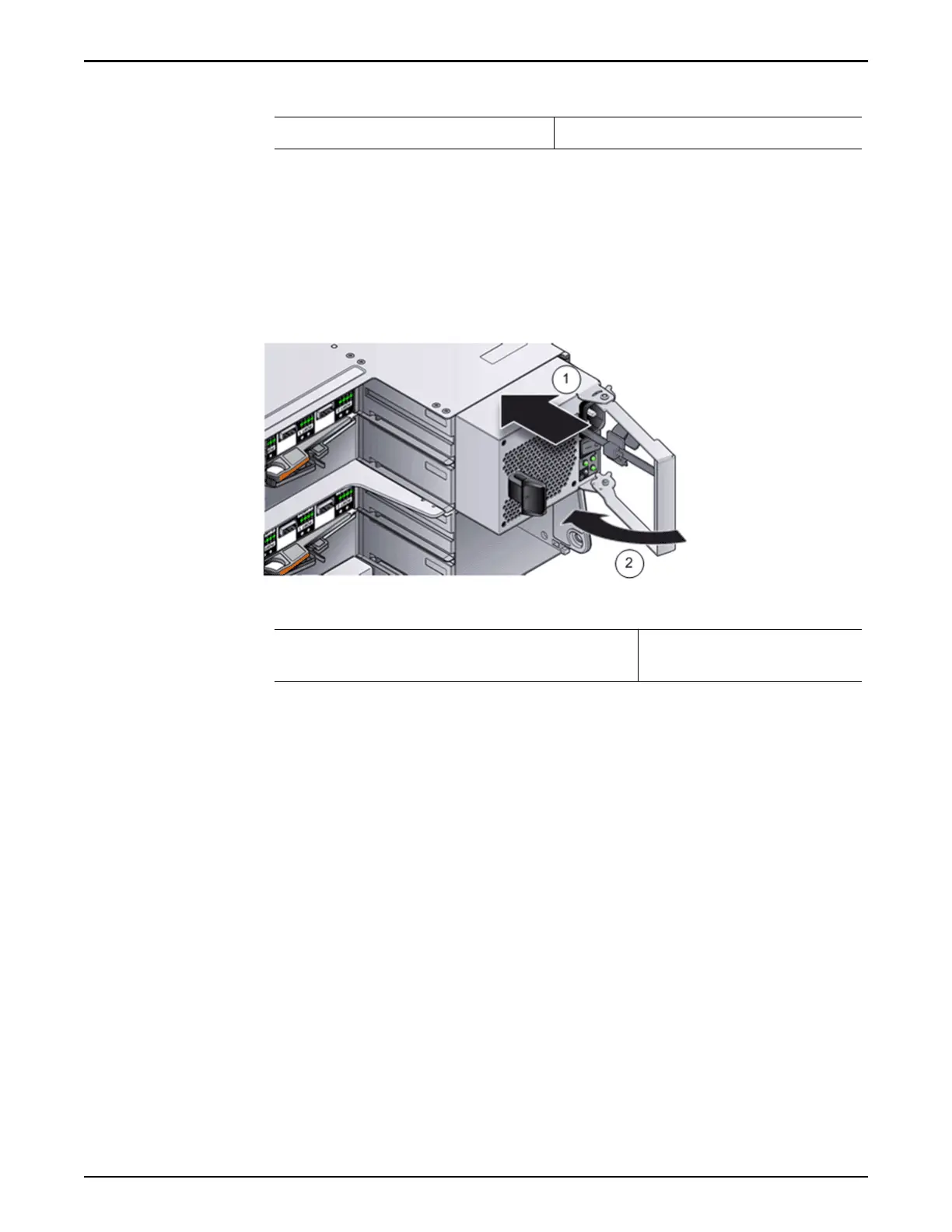
Figure 142: Power cooling module (right side)
Legend
1 Slide replacement power cooling module
into Driv
e Enclosure chassis slot
2 Close the aachment
lever
3 Make sure that the pow
er switch is o for the power cooling module.
4 Plug the power cord into the power cooling module.
5 Aach the power cord tie strap to the power cord.
6 Power on the replacement power cooling module.
When the power-on process completes, the following indicators should be
present:
•
The Power status LED emits a steady green light.
•
All other LEDs are o.
Verify the Status of a Drive Enclosure Component
1 From Guided Maintenance, verify that the status of the component is
Normal.
Guided Maintenance displays a message stating the component status. A
status of Normal requires no action.
2 Close Guided Maintenance.
Drive Enclosure Replacement Procedures
172