Controller Power Supply LED Indicators
The LED indicators on the pow
er supplies are at the left of the fan of each power
supply and provide power activity status.
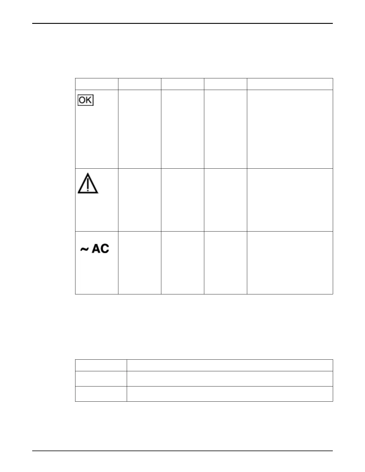
Table 33: Controller power supply LED status and description
Icon Location Name Color Status and meaning
Top OK Green
•
On – P
ower supply
is functional
without fault.
•
O – Power supply
is o or
initializing.
•
Flashing – No
function.
Middle Aention
Service
Required
Amber
•
On – Normal fault
detected.
•
O – No faults
detected.
•
Flashing – No
function.
Boom AC or DC Green
•
On – Input pow
er
present and good.
•
O – Input power
not present.
•
Flashing – No
function.
Controller Fan LED Indicators
A
single bi-color LED represents the status of each fan module. The LEDs are on
the motherboard near each fan module, and are visible from the back panel of
the Controller when you look through the grill below the risers.
Table 34: Controller fan LED status and description
Color Status and meaning
Green The fan module is functional without fault.
Amber The fan module has experienced a fault.
Note: There are tw
o LEDs near the status LED for the third fan module. Do not
confuse the FPGA Good and FPGA Diagnostic LEDs with the status LED for the
third fan module.
Oracle FS System LED Status
248