Replace a Pilot Riser
Riser board assemblies include printed circuit boards and PCIe slots in which
HBAs can be inserted based on system type and conguration.
A failed riser
board assembly can cause read and write errors because the HBAs will not be
able to function properly. Replace a failed riser board as soon as possible.
Prerequisites:
•
Before handling a component, touch a grounded surface to discharge any
static electricity.
• Aach an electrostatic discharge (ESD) wrist strap to your wrist, and stand
on an ESD mat while replacing components.
• Ensure that you have a Phillips Number 2 screwdriver with at least a 4-inch
shaft.
• Fail over the Pilot before replacing the component using Guided
Maintenance.
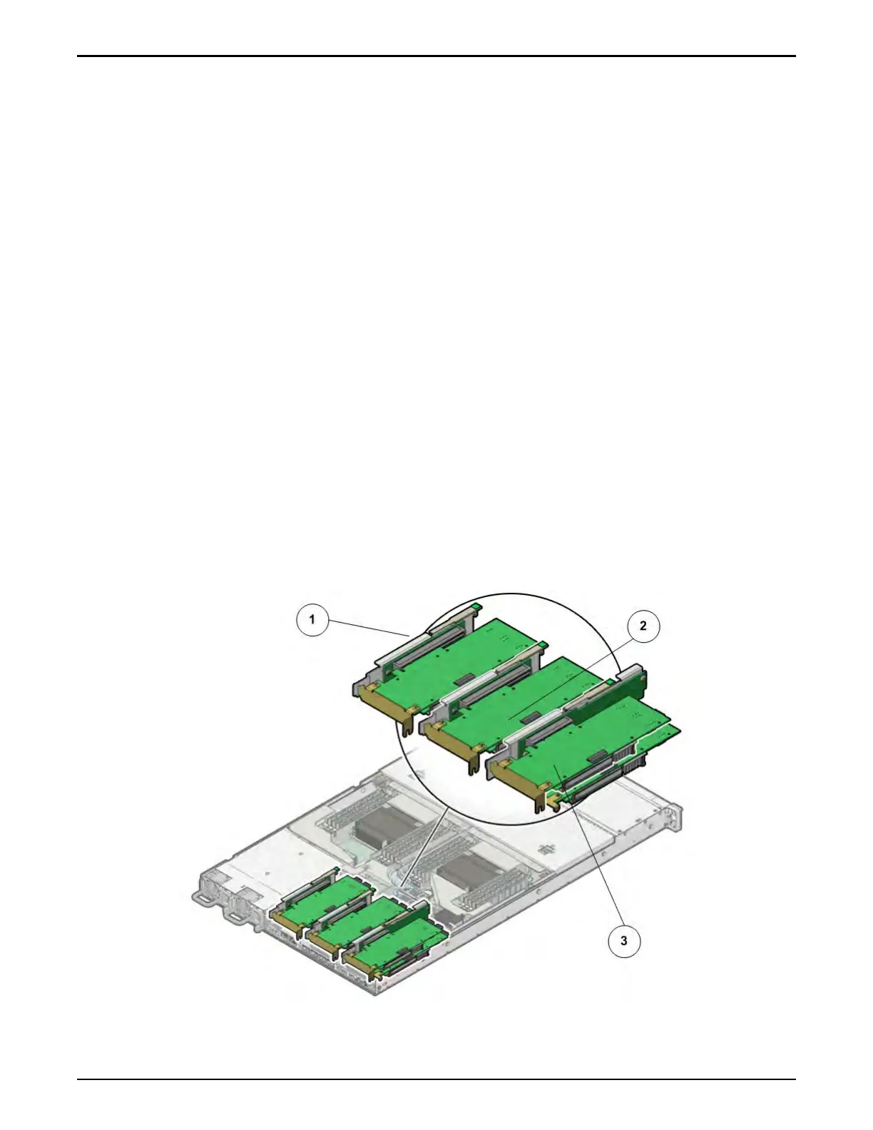
Each Pilot contains three riser board assemblies (R1 to R3 – left to right) located
side-by-side at the back of the Pilot
next to the power supplies. Risers are
customer replaceable units (CRUs). The SAS HBA is the only HBA that is
inserted into the Pilot riser. Replacing a riser requires you to power o the Pilot.
The following gure shows the location of the riser board assemblies on the Pilot
motherboard.
Figure 166: Riser locations
Pilot Replacement Procedures
198