List of Figures
Figure 1: Controller
back view...................................................................................................21
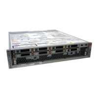
Figure 2: Controller front view with the air filter.........................................................................22
Figure 3: Controller front view without the air filter....................................................................22
Figure 4: Exploded view of Controller replaceable components...............................................23
Figure 5: DE2-24P Drive Enclosure CRUs................................................................................25
Figure 6: DE2-24C Drive Enclosure CRUs................................................................................26
Figure 7: Pilot back view............................................................................................................28
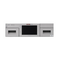
Figure 8: Pilot front view............................................................................................................29
Figure 9: Exploded view of Pilot replaceable components........................................................30
Figure 10: Component numbering in Oracle FS Systems.........................................................42
Figure 11: Examples of supported rack holes...........................................................................44
Figure 12: Controller rack mount location..................................................................................46
Figure 13: Left rail secured to the front of the rack....................................................................47
Figure 14: Left rail adjusted at the back of the rack ..................................................................48
Figure 15: Slide rail assembly unlocked....................................................................................49
Figure 16: Mounting bracket release button .............................................................................49
Figure 17: Slide rail middle section unlocked............................................................................50
Figure 18: Mounting bracket attached to the chassis................................................................51
Figure 19: Slide rail mounted on the rack post..........................................................................52
Figure 20: Slide rail spacing tool ..............................................................................................53
Figure 21: Controller chassis mounted on the slide rails ..........................................................54
Figure 22: CMA rail extension inserted into the back of the left slide rail .................................55
Figure 23: Inner CMA connector mounted................................................................................56
Figure 24: Outer CMA connector attached................................................................................56
Figure 25: Left side of the slide rail mounted.............................................................................57
Figure 26: Controller slide rails unlocked..................................................................................59
11
 Loading...
