Note: The CMA
in the graphic is for representation only. The CMA
shipped with your Pilot might be slightly dierent.
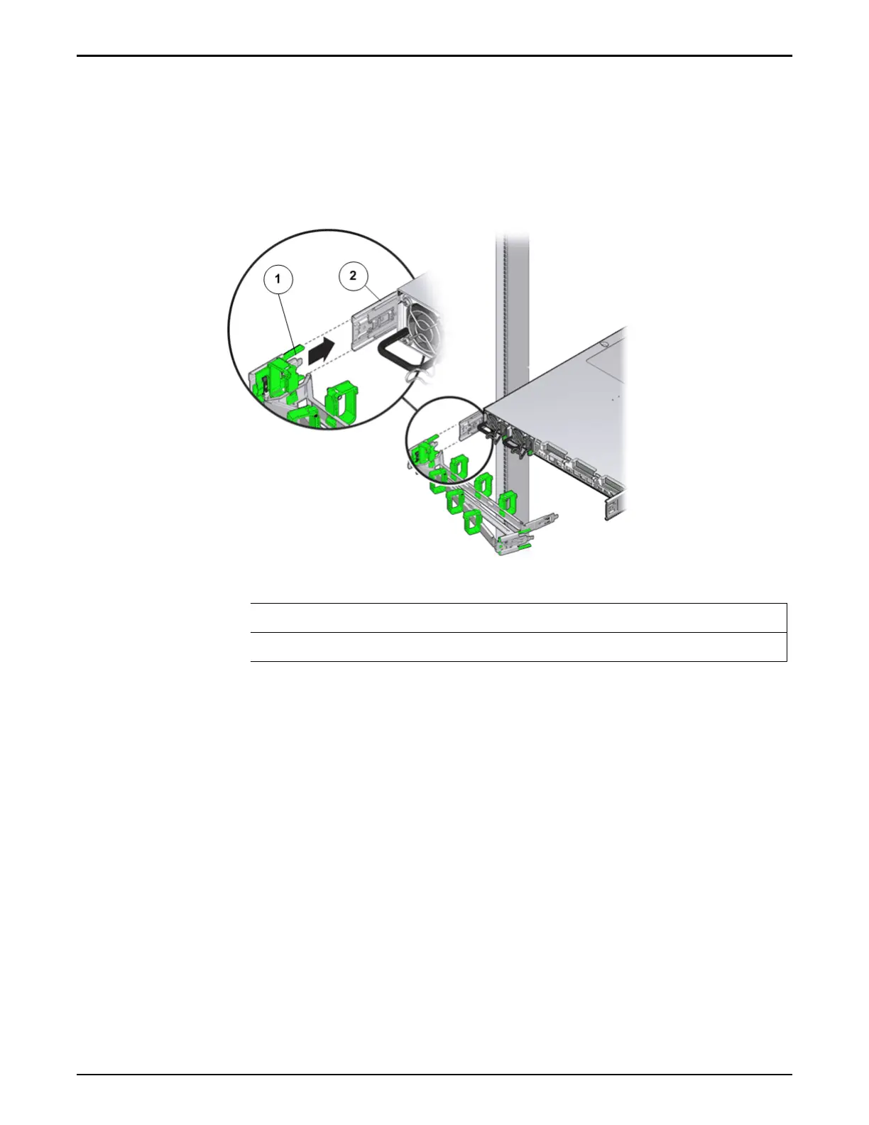
6 Insert the left CMA slide-rail connector into the back of the left slide rail
assembly until the connector locks into place with an audible click.
Figure 56: CMA slide rail connector inserted into the back of the left slide
rail
Legend
1 CMA slide rail connector
2 Left slide rail
Note: The CMA
in the graphic is for representation only. The CMA
shipped with your Pilot might be slightly dierent.
7 Install and route cables to the Pilot, as required.
Insert the Pilot into a Rack
Prerequisites:
•
Before handling a component, touch a grounded surface to discharge any
static electricity.
• Aach an electrostatic discharge (ESD) wrist strap to your wrist, and ensure
that you have an ESD mat. Stand on the ESD mat while replacing
components
Caution: Do not connect the PDUs to any external pow
er source until all
components and internal cables have been installed.
Caution: Turn o all the PDUs or do not connect component power cords to
PDUs until all components have been installed and all internal private
Oracle FS1–2 Global Procedures
86