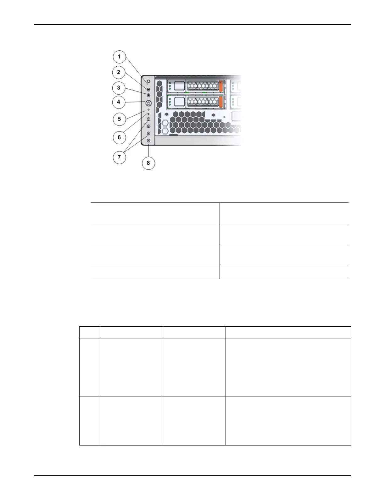
Figure 194: LED alarm assembly front display
Legend
1 Chassis identication LED or Locator
LED
5 Service processor LEDs
2 Service Action Required LED or
Caution or Fault LED
6 Back power supply LED
3 Motherboard or Power or OK LED 7 Fault or Alarm LEDs (Critical, Major,
Minor)
4 Power switch 8 User Alarm LED
The following table provides status information on the LEDs on the front display
panel of the LED alarm assembly on the Controller:
Table 31: Controller LED status and description (front panel)
No. LED LED color Status
1
Chassis
identication LED
or
Locator LED
buon
White The Locator LED can be turned on to
identify a particular system. When on,
the LED blinks rapidly
. Pressing and
holding the Locator buon for 5
seconds lights up all the LEDs that are
controlled by ILOM for 15 seconds.
2
Service Action
Required LED
Amber Indicates that service is required.
Under some fault conditions,
individual component fault LEDs are
turned on in addition to the Service
Required LED.
Oracle FS System LED Status
242