Legend
1 Power supplies 6 Network port to opposite Controller
2 HBA slots 7 Network port to Pilot PMI
3 Server management port 8 Network port to opposite Controller
PMI
4 Network management port 9 Ports for NAS host connection
5 Serial link port to opposite
Controller
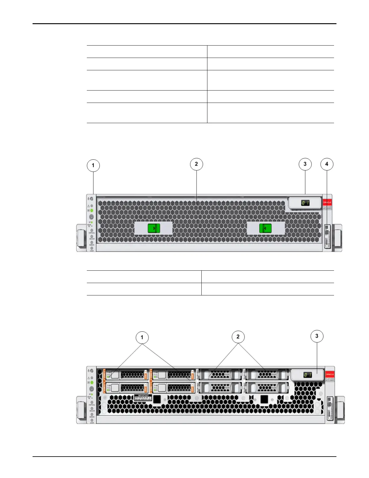
The following gure shows the front of the Controller with the air lter
.
Figure 2: Controller front view with the air filter
Legend
1 LED alarm board assembly 3 Controller identication display
2 Air lter 4 Controller RFID tag
The following gure shows the front of the Controller without the air lter.
Figure 3: Controller front view without the air filter
Introduction to Oracle FS1-2 System Service Procedures
22