Serial bus analysis
R&S
®
RTM3000
282User Manual 1335.9090.02 ─ 09
UART trigger settings
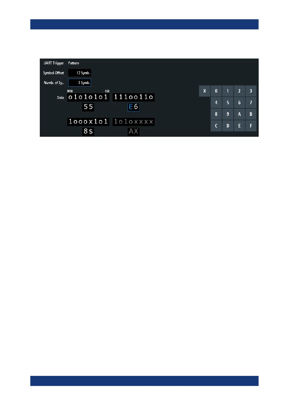
Figure 13-19: Trigger setup dialog with an example of a UART serial pattern
55 =
Hex value of the 1
st
symbol, with the binary value 01010101
E6 =
Hex value of the 2
nd
symbol, with the binary value 11100110
E (blue) =
Selected nibble in the 2
nd
symbol. The blue color indicates that the keypad is active for this nib-
ble.
8$ =
Hex value of the 3
rd
symbol. The 1
st
nibble has the binary value 1000 and the 2
nd
nibble is repre-
sented by the "$" character, as it includes one "X" bit (don't care)
AX (gray) =
The 4
th
symbol is not contained in the specified pattern
Source.........................................................................................................................282
UART Trigger.............................................................................................................. 282
Symbol Offset..............................................................................................................283
Numb. of Symb........................................................................................................... 283
Data.............................................................................................................................283
Source
Selects the transmitter or receiver line as trigger source.
Remote command:
TRIGger:A:SOURce:UART on page 632
UART Trigger
Selects the trigger condition.
"Start Bit"
Sets the trigger to the start bit. The start bit is the first logical 0 after a
stop bit.
"Frame Start"
Sets the trigger to the beginning of a frame. The frame start is the first
start bit after the idle time.
"Frame Error"
The instrument triggers, if a frame error occurs.
"Symbol <n>"
Sets the trigger to the specified symbol - the n-th word - in a frame
(package). Specify the "Symbol Offset" on page 283.
"Break"
Triggers if a start bit is not followed by a stop bit, the data line
remains at logic 0 for longer than a UART word.
"Parity Error"
Triggers on a parity error indicating a transmission error.
UART / RS232 (option R&S RTM-K2)
 Loading...


