Jitter analysis and clock data recovery
R&S
®
RTP
1015User Manual 1337.9952.02 ─ 12
Measurement Description/Result
Data rate Frequency of the clock signal. If no clock signal is available, it is recov-
ered by CDR. The measurement is based on the unit interval mea-
surement.
R
Clock k
= 1 / UI
k
for k = 1,...,K-1
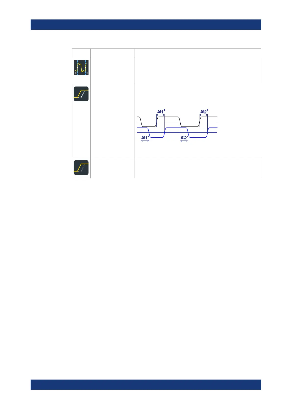
Skew delay Delay between the edges of two interdependent waveforms. The mea-
surement is a simplified variant of the "Delay" measurement assuming
that both sources are similar except for the delay.
Skew delay =
Δ
t
k
= t
Source2
- t
Source1
for k = 1,...,K
See also: Chapter 18.1.2.4, "Delay measurement settings",
on page 1020
Skew phase Phase difference between the edges of two waveforms.
Skew phase = Skew delay / Period * 360° =
Δ
t
k
/
Δ
T
Period k
* 360°
Limit and margin checks are also available for jitter measurements, see Chap-
ter 8.2.12, "Limit and margin checks", on page 396. Limit and margin checks are based
on the amplitude/time measurements.
18.1.2 Jitter measurement settings
18.1.2.1 Measurement selection
Access: [Meas] > "Meas Group" tab > "Jitter" category
Jitter measurements are only available for sources in the time domain.
Jitter measurements (Option R&S RTP-K12)

 Loading...


