Protocol analysis
R&S
®
RTP
680User Manual 1337.9952.02 ─ 12
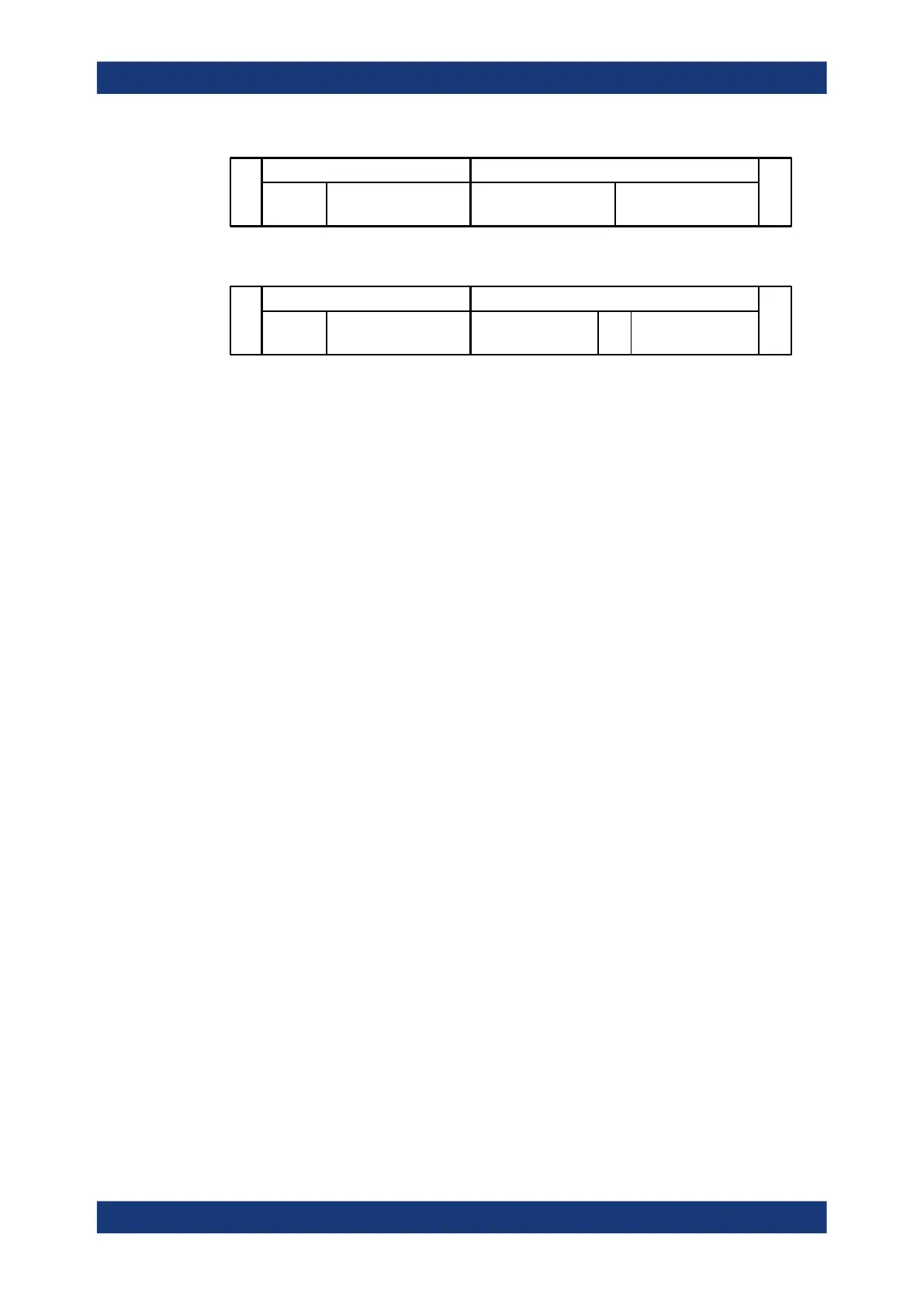
SSC
Command payload
8 bits + P
SA
4 bits
[Data frames]
8 bits + P
[Address frames]
8 bits + P
BP
Command frame Address and data frames
Figure 13-15: General structure of a RFFE Write command sequence
SSC
Command payload
8 bits + P
SA
4 bits
[Data frames]
8 bits + P
[Address frames]
8 bits + P
BP
Command frame Address and data frames
BP
Figure 13-16: General structure of a RFFE Read command sequence
Trigger
The R&S RTP uses a hardware-based trigger to trigger on various parts of slave
device messages, to trigger at maximum bus speed and on frame gaps. The data and
clock lines must be connected to the input channels. Triggering on math and reference
waveforms is not possible.
You can trigger on:
●
Start of command sequence (SSC). In addition, you can specify a slave address.
●
End of command sequence). In addition, you can specify a slave address.
●
Various errors, for example, parity and bus park error
●
Read and write command sequences between the BOM and the slaves.
Within a command sequence, you can trigger on specific parts of the message:
– Slave address
– Byte count
– Register address
– Data word
Search
Using the search functionality, you can find various events in the acquired and deco-
ded data. You can find the same events which you also can trigger on. In addition, you
can find command sequences of master-to master communication and "interrupt sum-
mary and identification" command sequences.
13.12.2 RFFE configuration
13.12.2.1 RFFE configuration settings
Access: [Protocol] > "Setup" tab > "Protocol" = RFFE
RFFE (option R&S
RTP-K40)

 Loading...


